3 Controller
Outside dimensions/Installation dimensions 3-54
3.3.2 Installation dimensions
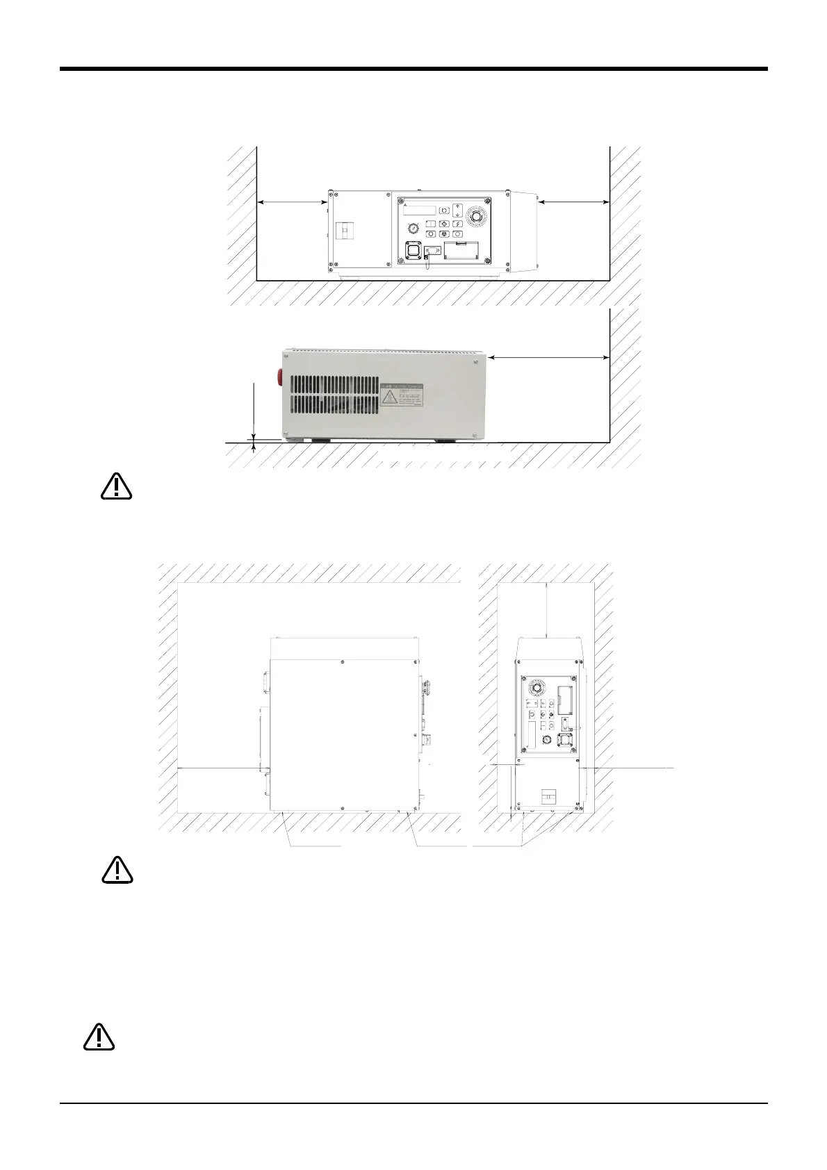
Fig.3-13 : Installation of controller(CR2DA-700 series)
When storing the controller in a cabinet, etc., take special care to the heat radiating
properties and ventilation properties so that the ambient temperature remains within the
specification values.
145
145
250
or more
7 or more
1
5
0
m
m
o
r
m
o
r
e
20mm or more
250mm or more
7
m
m
o
r
m
o
r
e
Rubber foot Rubber foot
Rubber foot
50mm or more
Use the rubber foot (4 positions) at the bottom of the controller as it is, or put the
spacer, and leave the space between the installation side and the controller
installation side more than 7mm when you fix the controller with the installation
screw. In smaller than 7mm case, the air intake hole at the bottom of the controller
is occupied, and temperature rises in the board, and causes the trouble.
CAUTION
The installation section needs to be fixed so that the controller may not fall.
When fixing the controller with the bolt, please use the bolt of the length which
does not protrude 5mm or more into the controller case.
CAUTION
(1) Remove the rubber foot at the bottom of the controller (four places, M5 x 10 screws).
(2) Remove the controller side white round seal (four places).
(3) Use the rubber foot and the 5xM10 screw which were removed by above-mentioned (1), and fix the rubber
foot to the screw hole of the seal pasting place of (2).
Horizontal placement
<CR2DA-700 series>
CAUTION
 Loading...


