EN-29
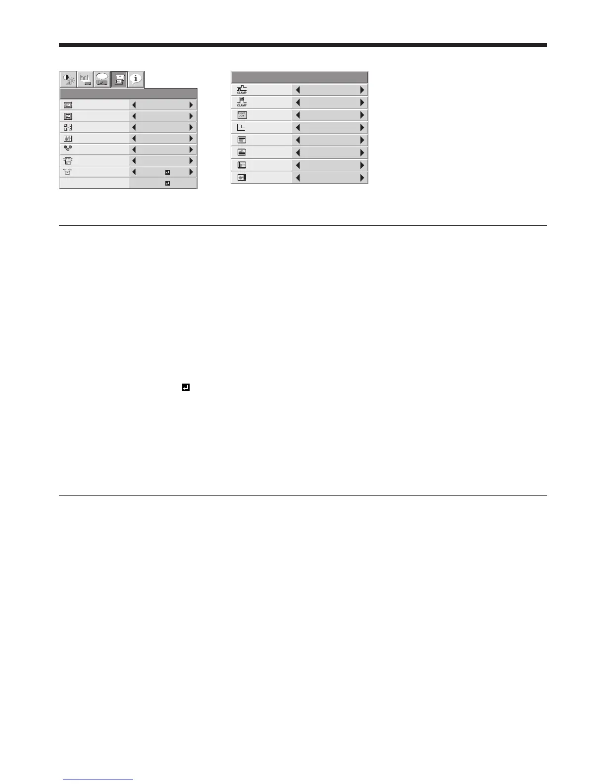
4. SIGNAL menu 5. USER menu
R G B
R G B
SIGNAL
HORIZ. POSITION 0
VERT. POSITION 0
TRACKING 0
COMPUTER
INPUT
AUTO
FINE SYNC. 0
USER
opt.
OK
ON
HOLD
100%
OVER SCAN
A V MEMO R Y 1
CLAMP
POSITION
USER
1
CLAMP WIDTH 1
LPF OFF
SHUTTER(U) 0
SHUTTER(L) 0
VERT. SYNC AUTO
?
SHUTTER(LS) 0
SHUTTER(RS) 0
Menu operation (continued)
4. SIGNAL menu
ITEM SETTING FUNCTION
HORIZ. POSITION
0 - 999 Use to adjust the horizontal position of the projected image.
VERT. POSITION
0 - 999 Use to adjust the vertical position of the projected image.
FINE SYNC. 0 - 31 Use to eliminate fl ickering or blur, if it appears, while viewing the projected
image.
TRACKING 0 - 9999 Use to eliminate vertical wide stripes, if it appears, while viewing the projected
image.
COMPUTER INPUT
AUTO The proper setting is automatically selected.
RGB Select this option when connecting the projector to high defi nition video
equipment having R, G, and B output terminals.
YC
B
C
R
/ YP
B
P
R
Select this option when connecting the projector to a DVD player or other
device having Y, C
B
, and C
R
(or Y, P
B
, and P
R
) component video output
terminals.
OVER SCAN 100 - 90% Use to adjust the display area of the projected image when playing LD and
DVD discs.
HOLD
OFF / ON
Use to adjust the image when fl agging occurs near the top of the screen.
Though horizontal strips may appear on the enlarged projected image, such symptom is not a malfunction.
When you change the horizontal or vertical position to a large extent, noise may appear.
The adjustable range of the vertical position varies depending on the type of the input signal. Though the image
may stay in the same position even when the setting value is changed, such symptom is not a malfunction.
If you increase the OVER SCAN setting when viewing video signals, noise may appear on the screen. In this case,
decrease the OVER SCAN setting.
5. USER menu
ITEM SETTING FUNCTION
CLAMP POSITION
1 - 255 Use to correct solid white or solid black in the projected image.
CLAMP WIDTH 1 - 63 Use to correct solid black in the projected image.
VERT. SYNC AUTO / OFF Use to adjust the image when its motion doesn’t run smoothly. Select AUTO for
normal use.
LPF ON / OFF Use to select whether or not to enable the LPF.
SHUTTER(U) 0 - 32 Use to display the black bar on the top part of the image.
SHUTTER(L) 0 - 32 Use to display the black bar on the bottom part of the image.
SHUTTER(LS) 0 - 95 Use to display the black bar on the left half of the image.
SHUTTER(RS) 0 - 95 Use to display the black bar on the right half of the image.
•
•
•
•
 Loading...