5.
ADJUSTMENTS
5.1
Thread
Trimmer
Mechanism
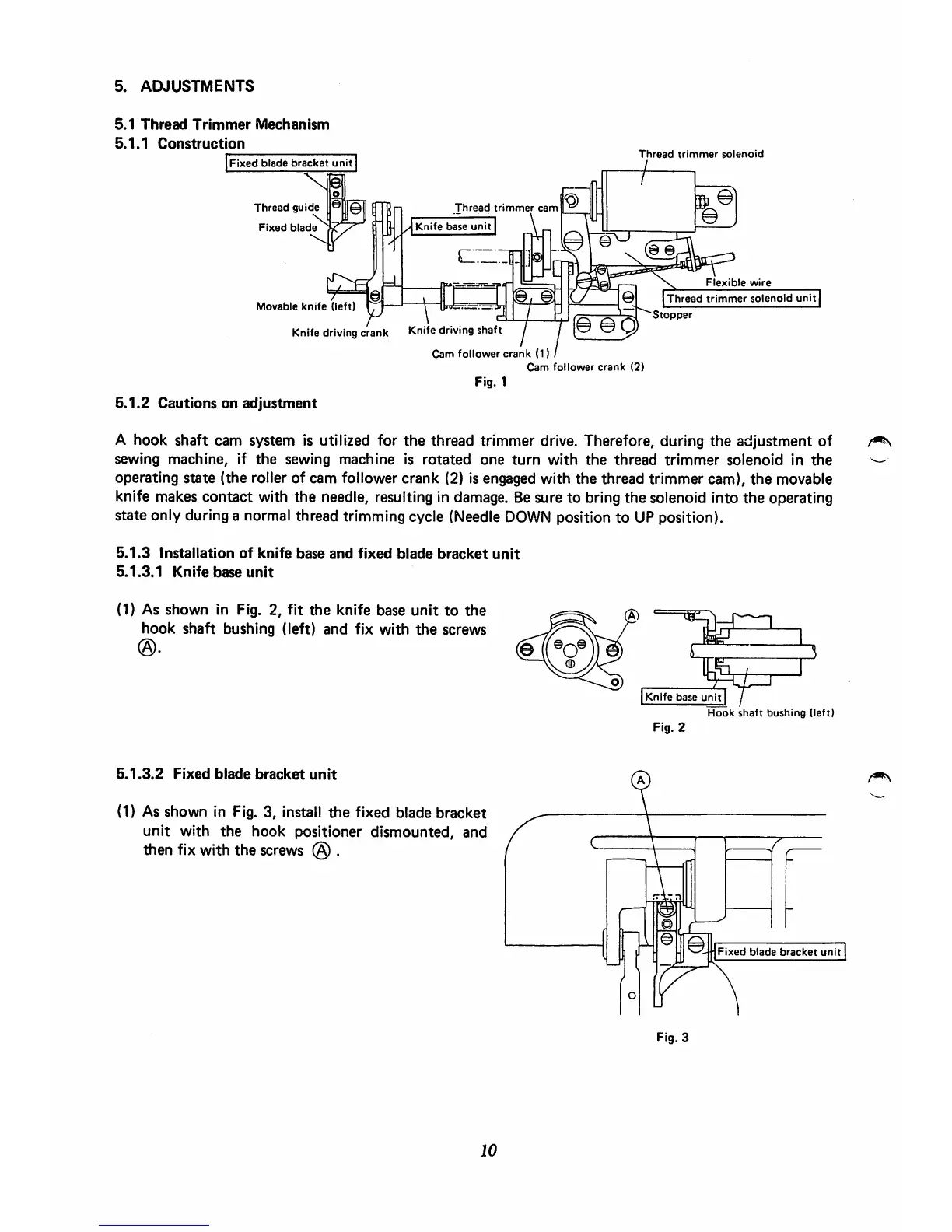
5.1.1
Construction
Fixed
blade
bracket
unit
Thread
guide
Fixed
blade
Movable
knife
(left)
Thread
trimmer
cam
^
Knife
base
unit
\
Knife
driving
crank
Knife
driving
shaft
Cam
follower
crank
(1)
Cam
follower
crank
(1)
Cam
follower
crank
(2)
Fig. 1
5.1.2
Cautions
on
adjustment
Thread
trimmer
solenoid
.s
e.
Flexible
wire
Thread
trimmer
solenoid
unit
Stopper
A hook shaft cam system is utilized for
the
thread trimmer drive. Therefore, during
the
adjustment
of
sewing machine, if
the
sewing
machine
is
rotated
one
turn
with
the
thread
trimmer
solenoid
in
the
operating state (the roller of cam follower crank (2) is engaged with
the
thread trimmer cam),
the
movable
knife makes contact with the needle, resulting in damage. Besure to bring the solenoid into the operating
state only during a normal thread trimming cycle (Needle
DOWN
position to UP position).
5.1.3
Installation
of
knife
base
and
fixed
blade
bracket
unit
5.1.3.1
Knife
base
unit
(1) As shown in Fig. 2, fit
the
knife base
unit
to
the
hook
shaft
bushing (left)
and
fix
with
the
screws
5.1.3.2
Fixed
blade
bracket
unit
(1) As shown In Fig. 3, install
the
fixed blade
bracket
unit
with
the
hook
positioner
dismounted,
and
then
fix
with
the
screws
@ .
10
Knife
base
unit
r
Hook
shaft
bushing
(left)
Fig. 2
Fixed
blade
bracket
unit
Fig. 3
 Loading...