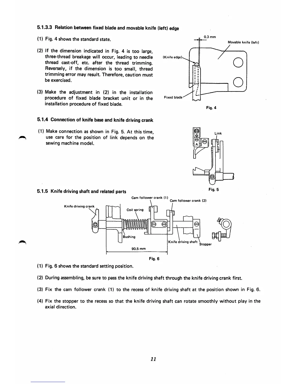
5.1.3.3
Relation
between
fixed
blade
and
movable
knife
(left)
edge
(1) Fig. 4 shows
the
standard
state.
(2) If the dimension indicated in
Fig.
4 is too
large,
three-thread breakage
will
occur, leading to needle
thread cast-off, etc. after the thread trimming.
Reversely, if
the
dimension is
too
small, thread
trimming error may result. Therefore, caution must
be
exercised.
(3) Make the adjustment in (2) in
the
installation
procedure
of
fixed
blade
bracket
unit
or
in
the
installation
procedure
of
fixed
blade.
5.1.4 Connection of knife base and knife drivingcrank
(1) Make connection as shown in
Fig.
5. At this time,
use care for
the
position of link depends on
the
sewing
machine
model.
5.1.5
Knife driving
shaft
and
related
parts
(Knife
edge)
Fixed
blade
0.3
mm
Fig. 4
Link
Fig. 5
Cam
follower
crank
(1)
Coil
spring
irer
crc
Cam
follower
crank
(2)
Knife
driving
crank
\
Bushing
30.5
mm
n
a
Knife
driving
shaft
Stopper
Movable
knife
(left)
/
Fig. 6
(1) Fig. 6 shows
the
standard setting position.
(2) Duringassembling, be sure to pass the knife drivingshaft through the knife drivingcrank first.
(3) Fix
the
cam follower
crank
(1)
to
the
recess
of
knife driving
shaft
at
the
position
shown
in Fig. 6.
(4)
Fix
the
stopper
to
the
recess so
that
the
knife
driving
shaft
can
rotate
smoothly
without
play
in
the
axial
direction.
11
 Loading...