4 - 34
CPU MODULE4.
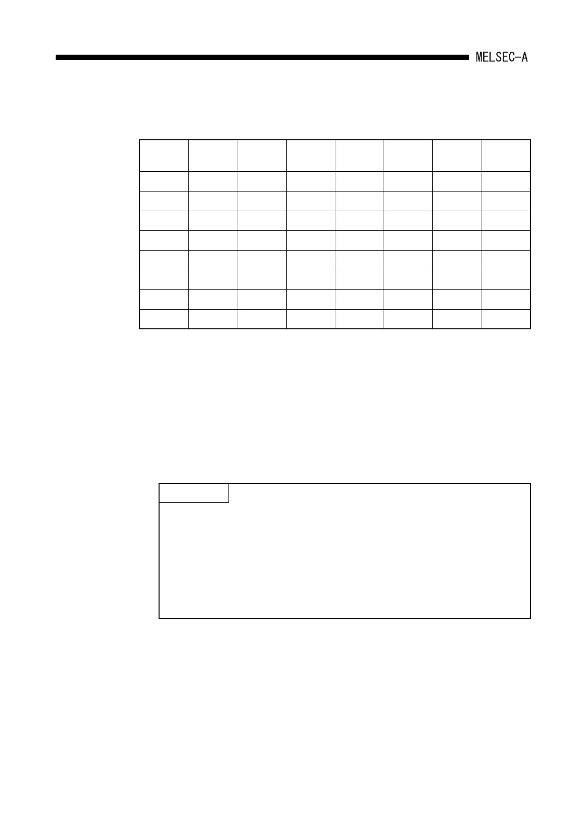
The interrupt counters in C224 to C255 are allocated to the interrupt pointers I0 to I31 as
shown below, and count the occurrences of interrupts by those of I0 to I31.
(d) The counter-use points can be set arbitrarily by 16 points using the serial
numbers.
By setting the counter which points to the number actually used, the counter
processing time subsequent to the END instruction can be shortened.
(e) The counter set values are as follows:
Interrupt
pointer
Interrupt
counter
Interrupt
pointer
Interrupt
counter
Interrupt
pointer
Interrupt
counter
Interrupt
pointer
Interrupt
counter
I0 C224 I8 C232 I16 C240 I24 C248
I1 C225 I9 C233 I17 C241 I25 C249
I2 C226 I10 C234 I18 C244 I26 C250
I3 C227 I11 C235 I19 C243 I27 C251
I4 C228 I12 C236 I20 C244 I28 C252
I5 C229 I13 C237 I21 C245 I29 C253
I6 C230 I14 C238 I22 C246 I30 C254
I7 C231 I15 C239 I23 C247 I31 C255
C0 to C255 :constant or word device (D)
C256 to C1023 :word device (D, W, R)
(Allocate a storage device for the set value by setting
parameters.)
POINT
When the timer-use points are set to 257 points or more or the counter-use points
are set to 257 points or more, the set value storage devices (D, W, R) specified at
the time of timer/counter use point setup are automatically set in the serial
numbers.
<Example>
When the timer-use points are set to 512 points and the set value storage device
is set to D1000, D equivalent to 256 points (D1000 to D1255) in T256 to T511
becomes the devices for the set values using the continuous numbers.
 Loading...


