5.
.
QPFMTING
>I*
*.
,
."
PROCEDURES
MELSEC-A
5.3.3
Display
format
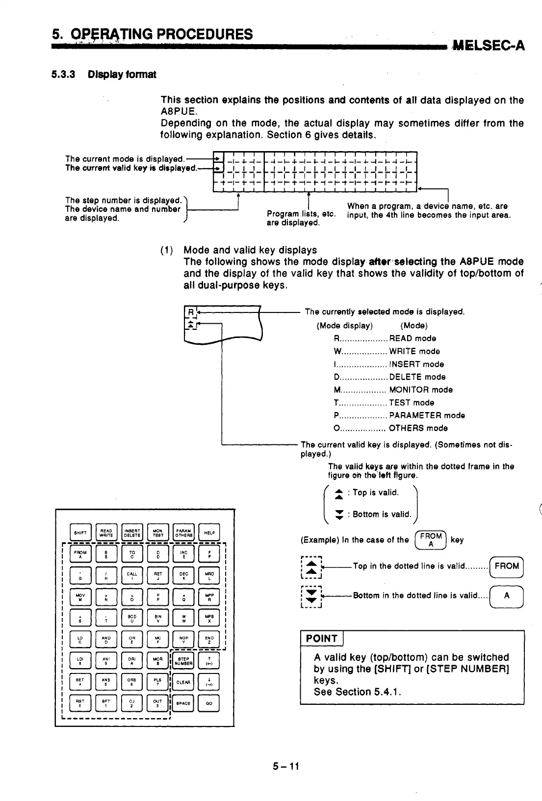
This section explains
the
positions
and
contents of
all
data displayed on the
A8PUE.
Depending on the mode, the actual display may sometimes differ from the
following explanation. Section
6
gives details.
The step number is displayed.
are displayed.
The device name and number
T
When
a
program, a device
I
name, etc. are
are displayed.
Program lists, etC. input, the 4th line becomes the input area.
(1)
Mode and valid key displays
The following shows the mode display aflerjselecting
the
A8PUE mode
and the display
of
the valid key that shows the validity of top/bottom of
5
all
dual-purpose keys.
?:
j-,'
,
The currenUy selected mode is displayed.
(Mode display) (Mode)
R
...................
READ mode
W
..................
WRITE mode
I
....................
INSERT mode
D
...................
DELETE mode
M
..................
MONITOR mode
T
...................
TEST mode
P
...................
PARAMETER mode
0
..................
OTHERS mode
I
The current valid key is displayed. (Sometimes not dis-
The valid
keys
arg within the dotted frame in the
figure
oi,
the.left figure.
played.)
I
(
2
:
Top is valid.
I
7
:
Bottom
is
valid.
I
(Example) In the
case
of the
(F)
key
r---y
I
A
'-Top in the dotted line is valid
.........
LA'
L
-Yi
---J
-Bottom in the dotted line is valid
r---y
....
A
valid key (top/bottom) can be switched
by using the
[SHIFT]
or [STEP NUMBER]
keys.
See Section
5.4.1.
,
J
b
i
!
i
i
i
I
i
,
If
5-
11
t

 Loading...


