5 - 23 5 - 23
MELSEC-Q/QnA
5 SEQUENCE INSTRUCTIONS
[Program Example]
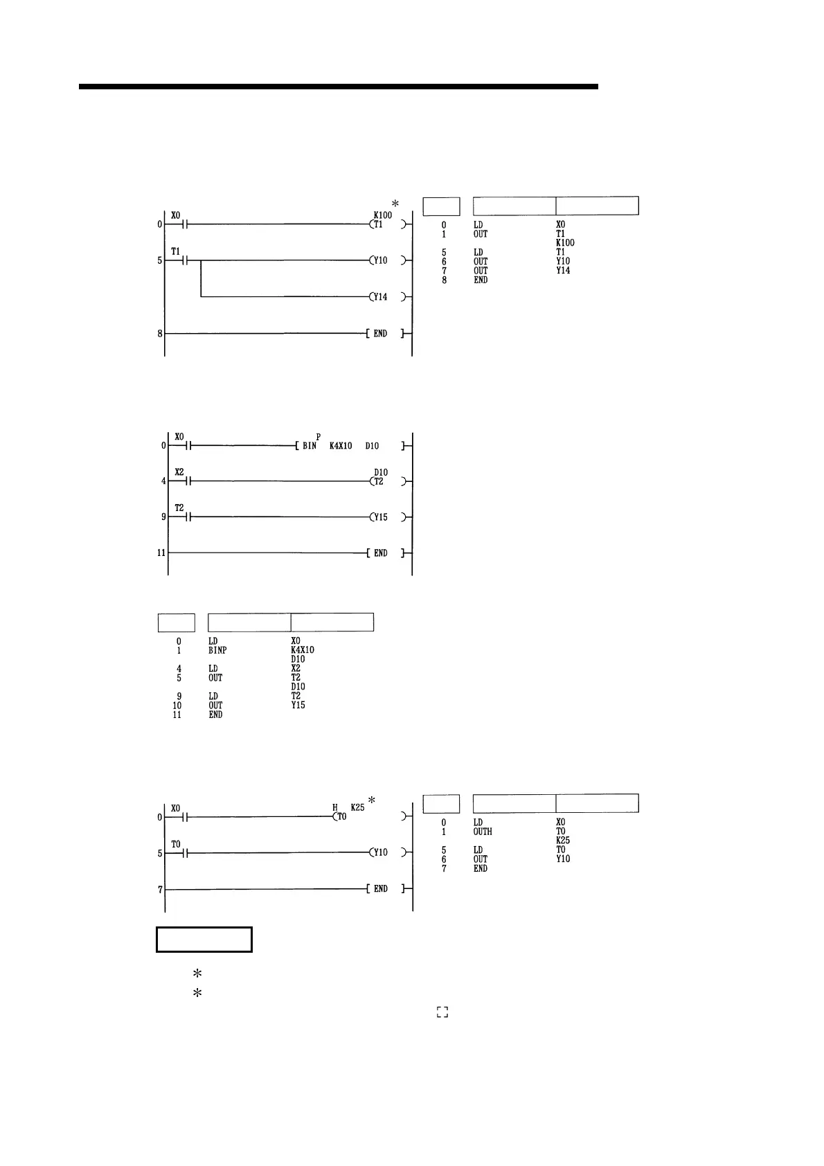
(1) The following program turns Y10 and Y14 ON 10 seconds after X0 has gone ON.
[Ladder Mode] [List Mode]
1
Steps
Instruction
Device
(2) The following program uses the BCD data at X10 to 1F as the timer's set value.
[Ladder Mode]
Converts BCD data at X10 to 1F to BIN
and stores at D10
When X2 goes ON, the data stored at
D10 is calculated as the set value.
Y15 goes ON when T2 counts out.
[List Mode]
Device
Steps
Instruction
(3) The following program turns Y10 ON 250 m after X0 goes ON.
[Ladder Mode] [List Mode]
2
Instruction
Steps
Device
REMARKS
(1) 1: The set value of the low speed timer indicates its default time limit (100 ms).
(2)
2: The set value of the high speed timer indicates its default time limit (10 ms)
(3) The number of basic steps of the OUT T instruction is 4.
Artisan Technology Group - Quality Instrumentation ... Guaranteed | (888) 88-SOURCE | www.artisantg.com

 Loading...


