2 - 6 2 - 6
MELSEC-Q/QnA
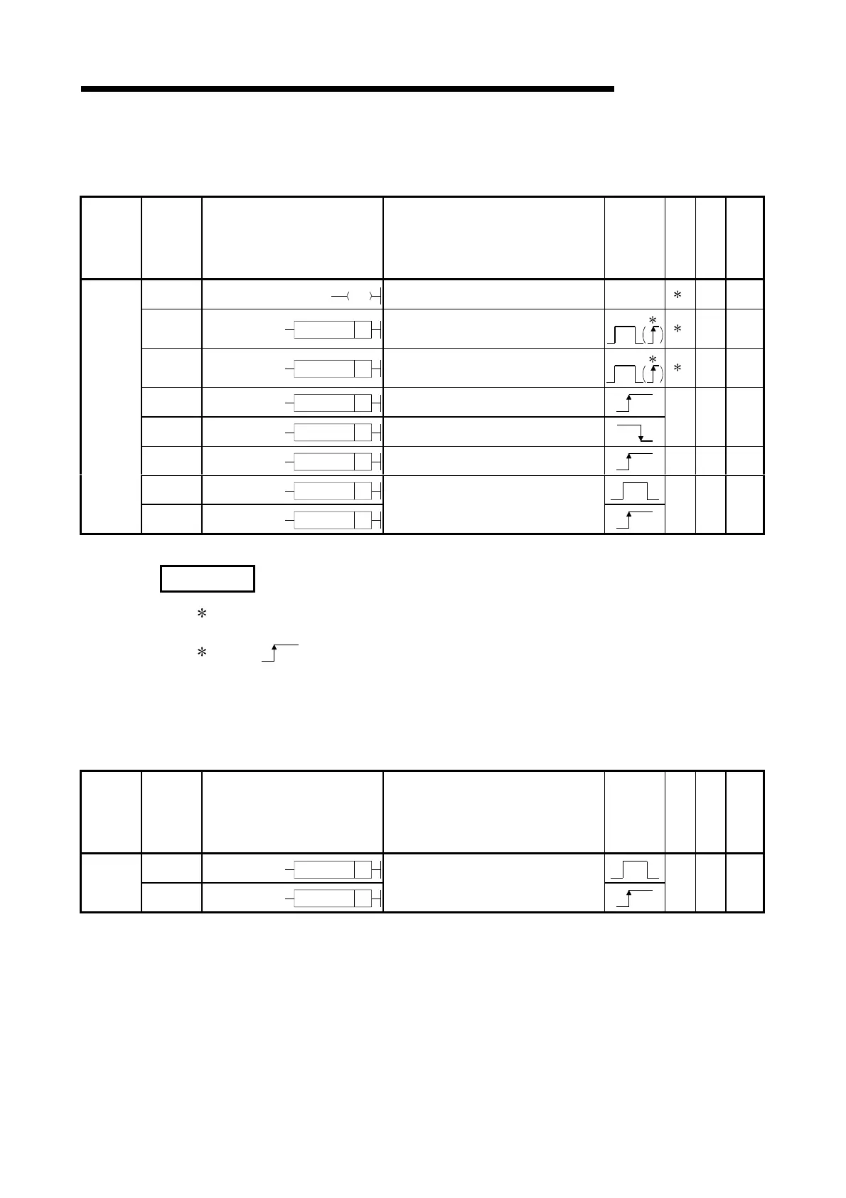
2 INSTRUCTION TABLES
2.3.3 Output instructions
Table 2.5 Output Instructions
Category
Instruction
Symbols
Symbol Processing Details
Execution
Condition
Number of
Basic Steps
Subset
See for
Description
OUT • Device output 15-18
SET
SET D
• Set device
2
1
5-28
5-32
RST
RST D
• Reset device
2
1
5-30
5-32
PLS
PLS D
• Generates 1 cycle program pulse at
leading edge of input signal
PLF PLF D
• Generates 1 cycle program pulse at trailing
edge of input signal
25-34
FF
FF
D
• Reversal of device output
25-36
DELTA
DELTA D
Output
DELTAP
DELTAP D
• Pulse conversion of direct output
25-38
REMARKS
1) 1: The number of steps may vary depending on the device in use.
See description pages of individual instructions for number of steps.
2)
2: The execution condition applies only when an annunciator (F) is in use.
2.3.4 Shift instructions
Table 2.6 Shift Instructions
Category
Instruction
Symbols
Symbol Processing Details
Execution
Condition
Number of
Basic Steps
Subset
See for
Description
SFT
SFT D
Shift
SFTP
SFTP D
• 1-bit shift of device
25-40
Artisan Technology Group - Quality Instrumentation ... Guaranteed | (888) 88-SOURCE | www.artisantg.com

 Loading...


