5 - 25 5 - 25
MELSEC-Q/QnA
5 SEQUENCE INSTRUCTIONS
(2) No count is conducted with the operation results at ON.
(There is no need to perform pulse conversion on count input.)
(3) After the count up status is reached, there is no change in the count value or the contacts until
the RST instruction is executed.
(4) A negative number (-32768 to -1) cannot be set as the setting value for the timer.
If the set value is 0, the processing is identical to that which takes place for 1.
(5) Index modification for the counter coil and contact can use only Z0 and Z1.
Index modification cannot be performed for the counter setting.
[Operation Errors]
(1) There are no operation errors associated with the OUT C instruction.
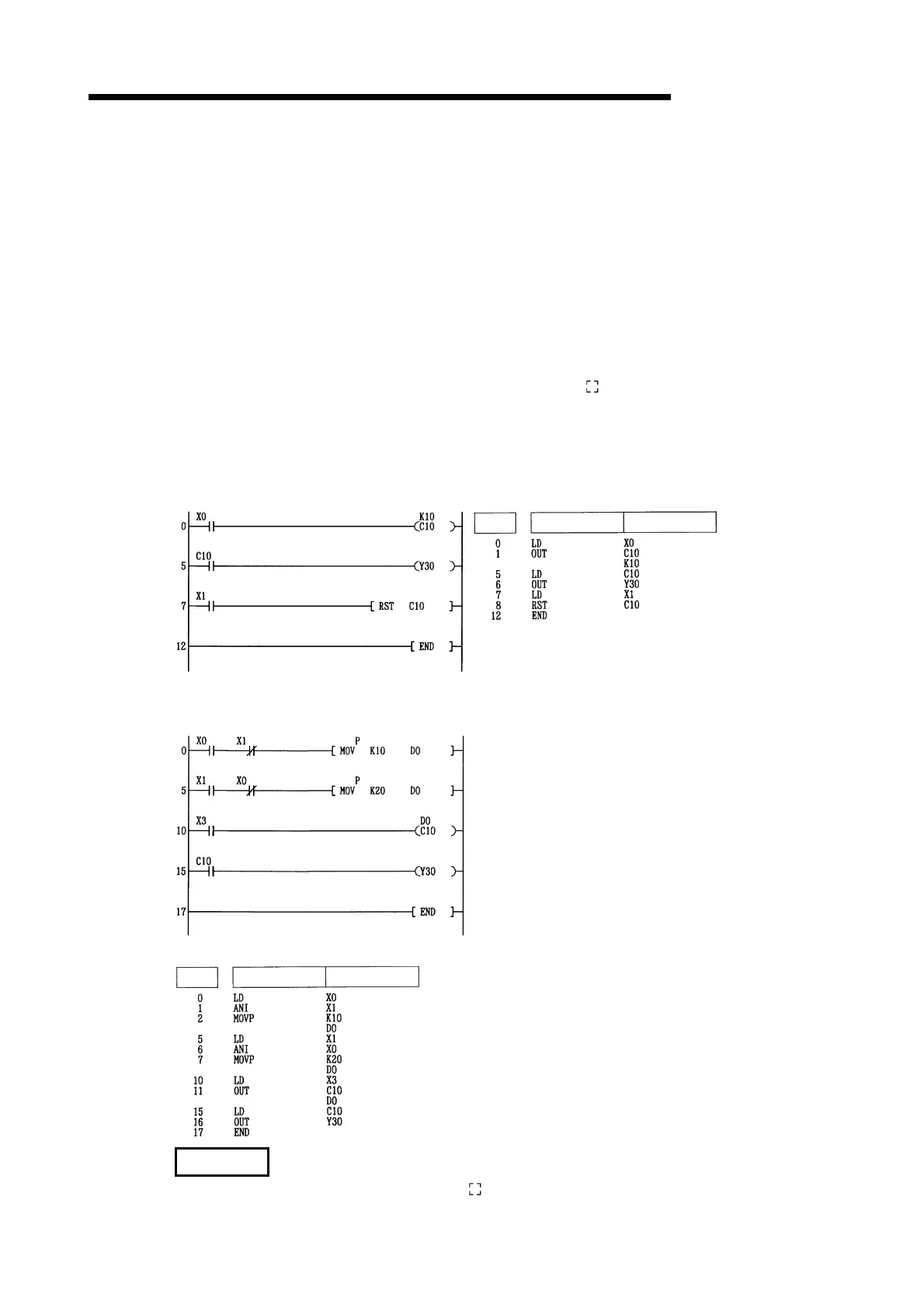
[Program Example]
(1) The following program turns Y30 ON after X0 has gone ON 10 times, and resets the counter
when X1 goes ON.
[Ladder Mode] [List Mode]
Device
Steps
Instruction
(2) The following program sets the value for C10 at 10 when X0 goes ON, and at 20 when X1 goes ON.
[Ladder Mode]
Stores 10 at D0 when X0 goes ON
Stores 20 at D0 when X1 goes ON
C10 takes data stored at D0 as set
value, and counts
Y30 goes ON when C10 reaches count
out state
[List Mode]
Steps
Instruction
Device
REMARK
The number of basic steps of the OUT C instruction is 4.
Artisan Technology Group - Quality Instrumentation ... Guaranteed | (888) 88-SOURCE | www.artisantg.com

 Loading...


