49
Table 6.4 Allowable Fault Conditions in Conductors
6.6 Protective Coordination with Wiring
6.6.1 General Considerations
If it is assumed that the heat generated by a large
current passing through a wire is entirely dissipated
within the wire, the following expression is applicable
(for copper wires):
(
S
I
2
t=5.05✕10
log
4
e
234+T
234+To
)
I : Current(A, rms)
S : Wire cross-sectional area(mm
2
)
t : Current let-through time(s)
T : Wire temperature due to short circuit(°C)
To : Wire temperature before short circuit(°C)
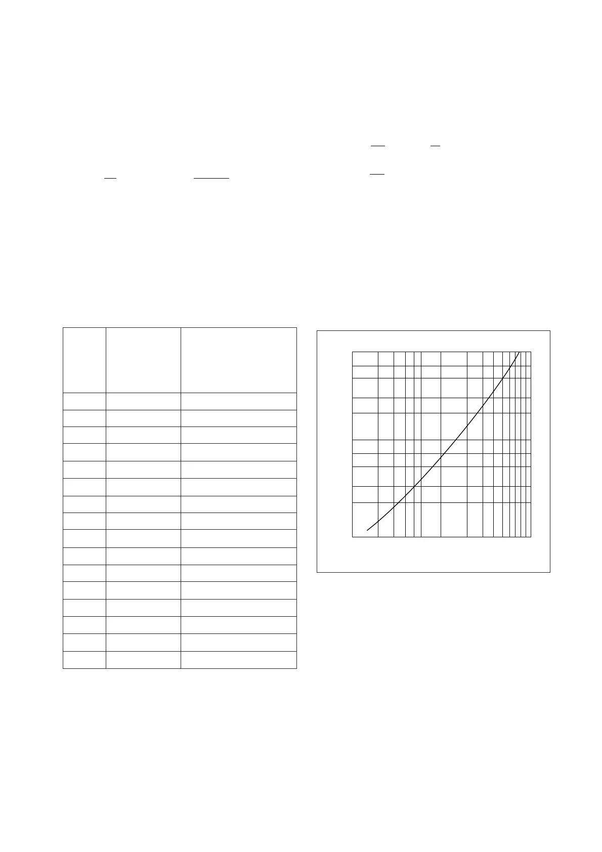
Assume that short-circuit current occurs in a wire car-
rying its rated current (hot state To=60°C). If 150°C is
the allowable temperature T, the following expression
is applicable (see also Fig. 6.13):
Is
Allowable short-circuit
current accoeding to I
2
t
kA, sym. (PF)
1
1.5
2.5
4
6
10
16
25
35
50
70
95
120
150
185
240
Allowable I
2
t
A
2
✕s
S
Wire size
mm
2
Notes: 1. Allowable I
2
t is calculated assuming that
all heat energy is dissipated in the
conductor, conductor allowable maximum
temperature exceeds 150°C, and hot
start is applied, at 60°C.
2. I
s
is an asym. value of allowable short-
circuit current reduced to below the
allowable I
2
t, assuming half cycle
interruption for 16mm
2
or less and one
cycle interruption for 25mm
2
or more.
Allowable I
2
t=14000S
2
Considering let-through energy (∫i
2
dt) in a fault where
the protector has no current-limiting capability, if short-
circuit occurs when let-through current is max., ∫i
2
dt
is:
where current le is the effective value of the AC com-
ponent. Half-cycle interruption is applied to wire of up
to 14mm
2
, and one-cycle interruption to larger wires.
Table 6.4 is restrictive in that, e.g., in a circuit of fault
capacity of 5000A or more, 2.5mm
2
wires would not
be permitted. In practice, the impedance of the con-
ductor itself presents a limiting factor, as does the in-
herent impedance of the MCCB, giving finite let-
through I
2
t and Ip values that determine the actual
fault-current flow.
6.6.2 600V Vinyl-Insulated Wire (Overcurrent)
Japanese Electrical Installations Technical Standards
(domestic) specify vinyl-insulated wire operating tem-
perature as 60°C max., being a 30°C rise over a 30°C
ambient temperature. This is to offset aging deterio-
ration attendant on elevated temperatures over long
periods. Criteria for elevated temperatures over short
periods have been presented in a study by B. W. Jones
and J. A. Scott (“Short-Time Current Ratings for Air-
craft Wire and Cable,” AIEE Transactions), which pro-
poses 150°C for periods of up to 2 seconds, and 100°C
for periods in the order of 20 seconds. These criteria
can be transposed to currents for different wire sizes
by the curves given in Fig. 6.14. Such figures, how-
ever, must be further compensated for the difference
between vinyl materials used for aircraft and for
0.014✕10
6
0.032✕10
6
0.088✕10
6
0.224✕10
6
0.504✕10
6
1.40✕10
6
3.58✕10
6
8.75✕10
6
17.2✕10
6
35.0✕10
6
68.6✕10
6
126✕10
6
202✕10
6
315✕10
6
479✕10
6
806✕10
6
1.17 (0.9)
1.76 (0.9)
2.93 (0.9)
4.68 (0.9)
6.79 (0.8)
10.5 (0.6)
16.0 (0.5)
17.3 (0.3)
24.2 (0.3)
34.5 (0.3)
48.3 (0.3)
65.6 (0.3)
82.8 (0.3)
103 (0.3)
128 (0.3)
166 (0.3)
Fig. 6.13 Temperature Rises Due to Current Flow in Copper Wires
×10
3
×10
4
Temperature rise(°C)
1000
700
500
300
200
100
20
30
50
70
12 23344567856 1
(A/mm
2
)
2
·s
Approx.
71
Ie
2
(A ·s) in
2
2
1
cycle interruption
(Power factor is 0.5.)
Approx.
34
Ie
2
(A ·s) in 1
2
cycle interruption
(Power factor is 0.3.)
 Loading...