58
7.3 For Main Circuits
7.3.1 For Motor Loads
The method of “synthesized motors” is recommended
– that is, the branch-circuit loads to be connected are
divided into groups of motors to be started simulta-
neously (assumed), and then each group is regarded
as a single motor having a full-load current of the total
of the individual motors in the group. The groups are
regarded as being sequentially started.
The rating of the branch MCCB for the largest syn-
thesized motor is designated I
B
max., those of the
subsequent synthesized motors as I
1
, I
2
, ...I
n-1
. The
rating of the main MCCB becomes:
I
MAIN
= I
B
max + (I
1
+ I
2
+...I
n-1
) x D
where D is the demand factor (assumed as 1 if inde-
terminate).
7.3.2 For Lighting and Heating, and Mixed Loads
For lighting and heating loads the rating of the main
MCCB is given as the total of the branch MCCB rat-
ings times the demand factor. For cases where both
motor-load branches and lighting and heating
branches are served by a common main MCCB, the
summation procedures are handled separately, as
described in the foregoing, then grand-totalized to give
the main MCCB rating.
7.4 For Welding Circuits
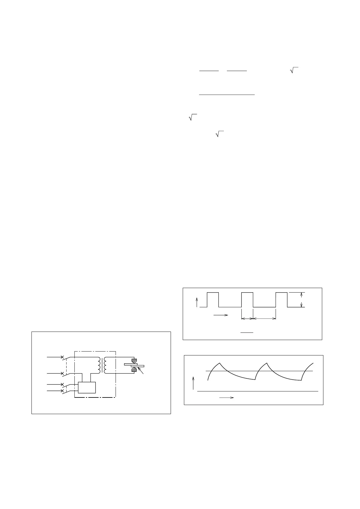
7.4.1 Spot Welders
A spot welder is characterized by a short, heavy in-
termittent load, switched on the transformer primary
side. The following points must be considered in
MCCB selection:
1. The intermittent load must be calculated in terms
of an equivalent continuous current.
2. The excitation transient surge due to the breaker
being on the transformer primary side must be al-
lowed for.
MCCB
Welder
Weld
workpiece
Control
timer
Supply
Fig. 7.3 Spot-Welder Circuit
The temperature rise of the MCCB and wiring de-
pends on the thermal-equivalent continuous current.
To convert the welder intermittent current into a ther-
mal-equivalent continuous value (I
e
), consider the
current waveform (Fig. 7.4); load resistance (R) gives
power dissipation:
W = I
1
2
Rt
1
and average heat produced:
t
1
+ t
2
W
=
t
1
+ t
2
I Rt
1
= I
1
2
Rβ = R(I
1
β )
2
1
where β is the duty factor, defined as
total conduction time
total time
This is equivalent to heating by a continuous current of
I
1
β
.
In the example of Fig. 7.4:
I
e
= I
1
β = 1200 x 0.0625 = 300 (A)
i.e., a continuous current of 300A will produce the
average temperature. In practice, however, the instan-
taneous temperature will fluctuate as shown in Fig.
7.5 and the maximum value (T
m
) will be greater than
the average (T
e
) that would be produced by a con-
tinuous current of 300A. The operation of an MCCB
thermal element depends on the maximum rather than
the average temperature, so it must be selected not
to trip at T
m
; in other words, it is necessary to ensure
that its hot-start trip delay is at least as great as the
interval of current flow in the circuit. The rated current
of a “mag-only” MCCB (which does not incorporate a
thermal trip function) can be selected based on the
thermal equivalent current of the load, allowing a
margin of approximately 15% to the calculated value
to accommodate supply-voltage fluctuations, equip-
ment tolerance, etc. Thus:
I
MCCB
= I
e
x 1.15 = 300 x 1.15 = 345 (A)
The MCCB selected becomes the nearest standard
value above 345A.
I
1 = 1200A
Time
(Duty factor b = =0.0625)
Current
t
1
t
2
(3sec.) (45sec.)
3+45
3
Fig. 7.4 Welder Intermittent Current
Time
T
e
T
m
Temperature
Fig. 7.5 Temperature Due to Intermittent Current
For practical considerations, rather than basing
selection on welding conditions, the MCCB should be
selected to accommodate the maximum possible duty,
based on the capacity and specifications of the welder.
If the welder rated capacity, voltage and duty fac-
tor in Fig. 7.3 are 85kVA, 200V and 50% respectively,
the thermal-equivalent continuous current (I
e
) be-
 Loading...