6
3.1 General
The primary components are: a switching mechanism,
an automatic tripping device (and manual trip button),
contacts, an arc-extinguishing device, terminals and
a molded case.
3. CONSTRUCTION AND OPERATION
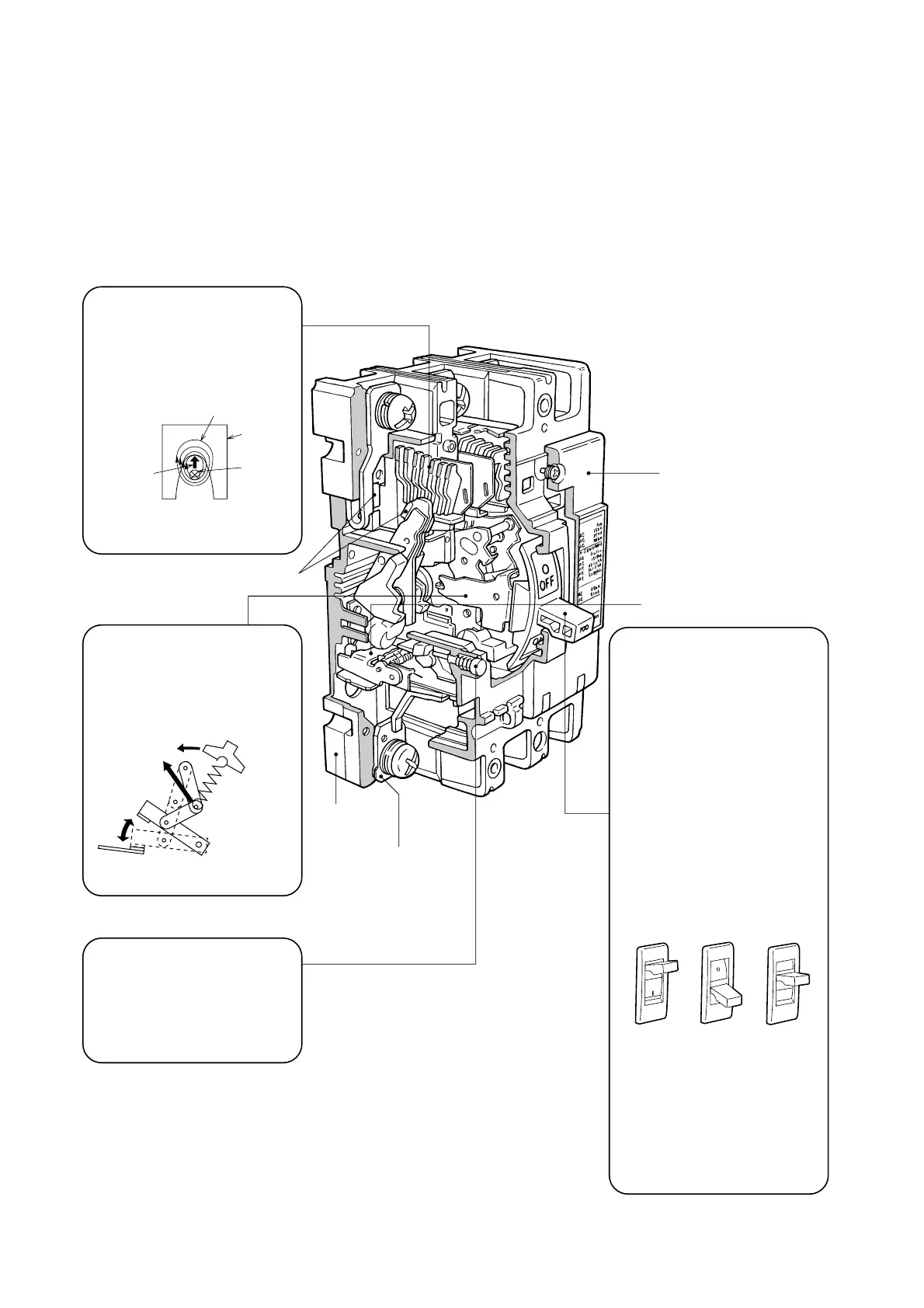
Fig. 3.1 Type NF100-SP Construction
Handle
1. Trip indication
The automatically tripped condi-
tion is indicated by the handle in
the center position between ON
and OFF, the yellow (or white)
line cannot be seen in this posi-
tion.
2. Resetting
Resetting after tripping is per-
formed by first moving the han-
dle to the OFF position to en-
gage the mechanism, then re-
turning the handle to ON to re-
close the circuit.
3. Trip-Free
Even if the handle is held at
ON, the breaker will trip if an
overcurrent flows.
4. Contact On Mechanism
Even in the worst case in which
welding occurs owing to an
overcurrent, the breaker will trip
and the handle will maintain to
ON, indicating the energizing
state.
ON OFF Trip
Handle indication
Arc-Extinguishing Device
Mitsubishi MCCBs feature excel-
lent arc-extinguishing perfor-
mance by virtue of the optimum
combination of grid gap, shape,
and material.
Trip Button (Push to Trip)
Enables tripping mechanically
from outside, for confirming the
operation of the accessory switch-
es and the manual resetting func-
tion.
Switching Mechanism
The contacts open and close rap-
idly, regardless of the moving
speed of the handle, minimizing
contact wear and ensuring safety.
Rapid
movement
Link-mechanism
operation
Magnetic flux
Arc extinction
Magnetic
force
Grid
Arc
Contact
Molded case
(Base)
Terminal
Molded case
(Cover)
Automatic tripping device
ON
OFF
ON
OFF
 Loading...