76
I
as
= I
s
· { 1 + 2e e+ 2 1 + } = I
s
· K
3
x
2πR
–
x
2πR
–
3
1
2
1
that is: K
3
= { 1 + 2e e+ 2 1 + }
x
2πR
–
x
2πR
–
3
1
2
1
K
3
is the asymmetrical coefficient, derived from the
symmetrical value and the circuit power factor.
3. Peak Value of Asymmetrical Short-Circuit Current
This value (I
p
in Fig. 9.3) depends upon the phase
angle at short circuit closing and on the circuit power
factor; it is maximum when θ = 0. It will reach peak
value in each case, ω
t
=
2
π
+ ϕ after the short circuit
occurrence. It can be computed as before, by means
of the circuit power factor and the symmetrical short-
circuit current.
I
p
= I
s
[1 + sinϕ·e ] = I
s
· K
p
2
π
x
R
–( + ϕ)·
thus: K
p
= 2 [1 + sinϕ·e ]
2
π
x
R
–( + ϕ)·
K
p
, the peak asymmetrical short-circuit current coeffi-
cient, is also known as the closing-capacity coefficient,
since I
p
is called the closing capacity. Thus, in each
case, the asymmetrical coefficients can be derived
from the symmetrical values and the circuit power fac-
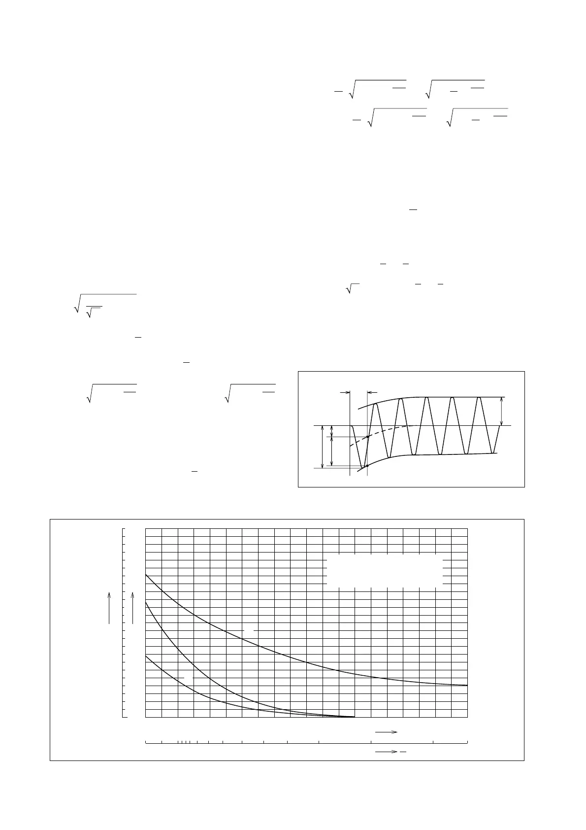
tor. These coefficients are shown Fig. 9.4.
A
s
A
s
1
/
2
Cycle
I
p
A
d
Fig. 9.3 Short-Circuit Current
9.4 Classification of Short-Circuit Current
A DC current (Fig. 9.3) of magnitude determined by
the voltage phase angle at the instant of short circuit
and-the circuit power factor will be superimposed on
the AC short-circuit current.
This DC component will rapidly decay; however,
where a high-speed circuit-interruption device such
as an MCCB or fuse is employed, the DC component
must be considered. Further, the mechanical stress
of the electric circuit will be affected by the maximum
instantaneous short-circuit current; hence, the short-
circuit current is divided, as below.
1. RMS Symmetrical Short-Circuit Current (I
s
)
This is the value exclusive of the DC component; it is
A
s
/M2 of Fig. 9.3.
2. RMS Asymmetrical Short-Circuit Current (I
as
)
This value includes the DC component. It is defined
as:
2
A
s
I
as
= )
2
+ A
d
2
(
Accordingly, when the DC component becomes maxi-
mum (i.e., θ – ϕ = ±
2
π
, where the voltage phase angle
at short circuit is θ, and the circuit power factor is cosϕ),
I
as
will also become maximum
2
1
cycle after the short
circuit occurs, as follows:
I
as
= I
s
· 1 + 2e = I
s
· K
1
, that is: K
1
= 1 + 2e
x
2πR
–
x
2πR
–
where K
1
is the single-phase maximum asymmetrical
coefficient, and I
as
can be calculated from the asym-
metrical value and the circuit power factor. In a 3-
phase circuit, since the voltage phase angle at switch-
on differs between phases, I
as
will do the same. If the
average of these values is taken
2
1
cycle later, to give
the 3-phase average asymmetrical short-circuit cur-
rent, the following relationship is obtained:
K
p
3.0
2.0
1.0
K
1
K
3
2.0
1.9
1.8
1.7
1.6
1.5
1.4
1.3
1.2
1.1
1.0
20 10 8 7 6 5 4 3 2.5 2 1.5 1 0.5
0.1 0.2 0.3 0.4 0.5 0.6 0.7 0.8 0.9 1.0
K
1
:
Single-phase maximum
asymmetrical coefficient
K
3
:
3-phase asymmetrical coefficient
K
p
:
Closing capacity coefficient
Power factor
R
X
K
p
K
1
K
3
Fig. 9.4 Short-Circuit Current Coefficients
 Loading...