68
7.8 Selection of MCCBs in inverter circuit
7.8.1 Cause of distorted-wave current
Distorted-wave current is caused by factors such as the CVCF device of a computer power unit, various recti-
fiers, induction motor control VVVF device corresponding to more recent energy-saving techniques, etc, wherein
thyristor and transistor are used. Any of these devices generates DC power utilizing the switching function of a
semiconductor and, in addition, transforms the generated DC power into intended AC power. Generally, a large
capacity capacitor is connected on its downstream side from the rectification circuit for smoothing the rectifica-
tion, so that the charged current for the capacitor flows in pulse form into the power circuit. Because voltage is
chopped at high frequency in AC to DC transforming process, load current to which high frequency current was
superimposed by chopping basic frequency flows into the load line. This paragraph describes the VVVF in-
verter, of these devices, which will develop further as main control methods for induction motors currently in
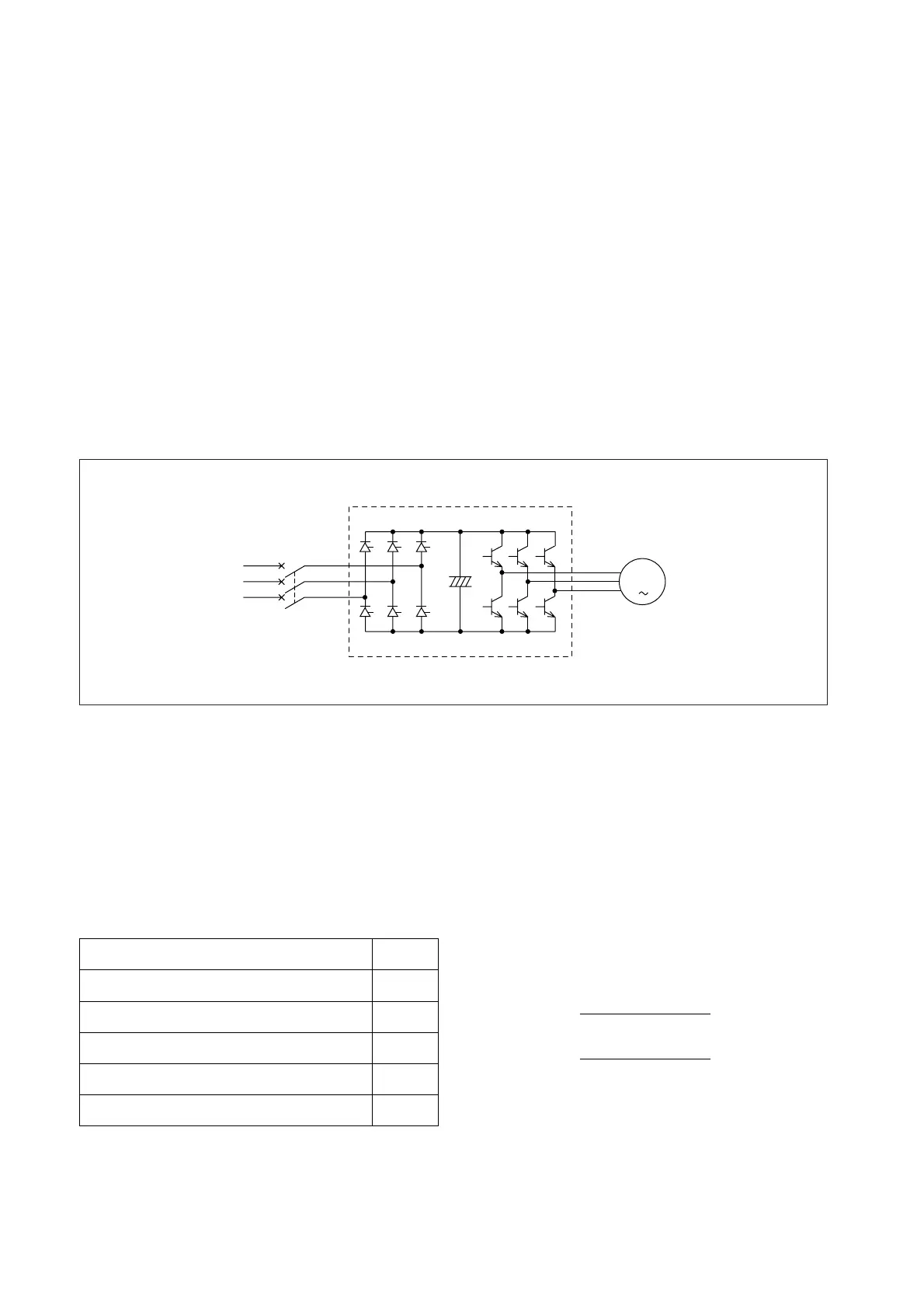
broad use in various fields . Fig. 7.27 illustrates an example of MCCBs application to inverter circuit. Two
control methods of PAM (Pulse Amplitude Modulation) and PWM (Pulse Wide Modulation) are available for the
VVVF inverter and generating higher harmonic wave components differs depending on the difference between
the control methods. As seen from Tables 7.9 and 7.10, this harmonic wave component of input current can be
made smaller (improved) by inputting DC reactor (DCL) or AC reactor (ACL). Further, in the case of the output
current waveform in Fig. 7.29, the PWM generates higher harmonic wave components than that of the PAM.
This table is subject to the current which meets the
following requirements.
Fig.7.27 Example of MCCBs Application to Inverter Circuit
Notes: 1. The characteristics of hydraulic-magnetic type MCCBs vary significantly depending on wave distor-
tion. Therefore, use of thermal-magnetic type MCCBs is recommended.
2. NF2000-S, NF2500-S, NF3200-S, NF4000-S
3. NFE2000-S, NFE3000-S, NFE4000-S
Table 7.8 Reduction Rate
q
Distortion factor
=
RMS value of total harmonic
wave component
RMS value of basic frequency
x 100 q 100% or less
w Peak factor =
Peak value
RMS value
q 3 or less
e Higher harmonic wave components are mainly No.7 or a lower
harmonic wave.
MCCBs tripping system
Thermal-magnetic (bimetal system)
1.4
2
1.4
1.4
2
(Note 2) Thermal-magnetic (CT system)
(Note 1) Hydraulic-magnetic
Electronic (RMS value detection)
(Note 3) Electronic (Peak value detection)
Reduction
rate K
7.8.2 Selection of MCCBs
MCCBs characteristic variations and temperature rises dependent on distortion of the current wave must be
considered when selecting MCCBs for application to an inverter circuit (power circuit). The relation of rated
current I
MCCB
to load current I of MCCBs is selected as follows from the MCCBs tripping system.
Thermal-magnetic type (bimetal system) and electronic type (RMS value detection) are both RMS current
detection systems which enable exact overload protection even under distorted-wave current. Due to the above
explanation, it is advantageous to select RMS current detection type MCCBs.
I
MCCB
Q
K x I
MCCB
M
Inverter
Induction motor
 Loading...