3 - 8 3 - 8
MELSEC-Q
3 SPECIFICATIONS
3.2.2 Master function (Message communication function)
The message communication function is used to get and set the attribute data of a
slave node.
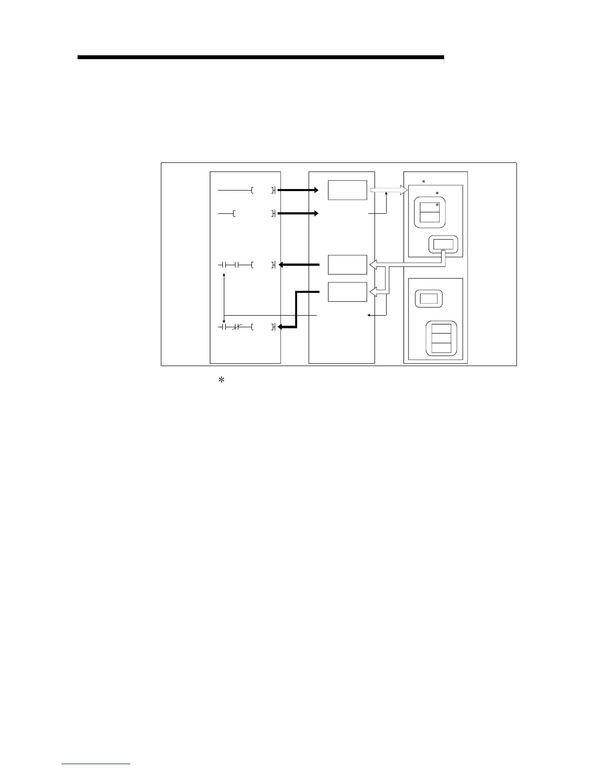
(1) Getting attributes
PLC CPU QJ71DN91 Slave node (MAC ID)
SET Y12
X02
FROM
Message
communication
request
1)
2)
6)
Message
communication
command area
0110
H
011F
H
5)
3)
TO
2)
X05
X02
FROM
X05
Message
communication
result area
0120
H
012F
H
Message
communication
data area
0130
H
01A7
H
Message
communication
complete
Message communication
completion
Class
Attribute
Instance
Class
4)
Attribute
Instance
Attribute
Instance
Attribute
Instance
Attribute
Attribute
Attribute
: In DeviceNet, the area used for reading and writing via communication
is specified by the numbers representing the class ID, instance ID, and
attribute ID. For details, refer to the manual of each slave node.
1) The TO instruction of the sequence program sets to get attributes in the
"message communication command" area of the buffer memory.
2) When the message communication request (Y12) is turned ON by the
sequence program, the data, which is set in the "message
communication command" area in the buffer memory, is sent to the
slave node and the message communication starts.
3) When the QJ71DN91 receives data from the slave node, it is processed
as follows:
• The specific data of the slave node that is set in the "message
communication command" area is stored in the "message
communication data" area of the buffer memory.
• The processing result of message communication is stored in the
"message communication result" area of the buffer memory.
4) The message communication is completed when the processing result
is stored in the "message communication result" area of the buffer
memory, and the message communication completion (X02) is
automatically turned ON.
5) Upon normal completion, the data in the slave node, which is stored in
the "message communication data" area of the buffer memory, is
loaded onto the PLC CPU by the FROM instruction of the sequence
program.
6) If the message communication error signal (X05) is turned ON, the
FROM instruction reads the contents of the "message communication
result" area, and the cause of the error is verified.

 Loading...