SERVICE DATA
2-9
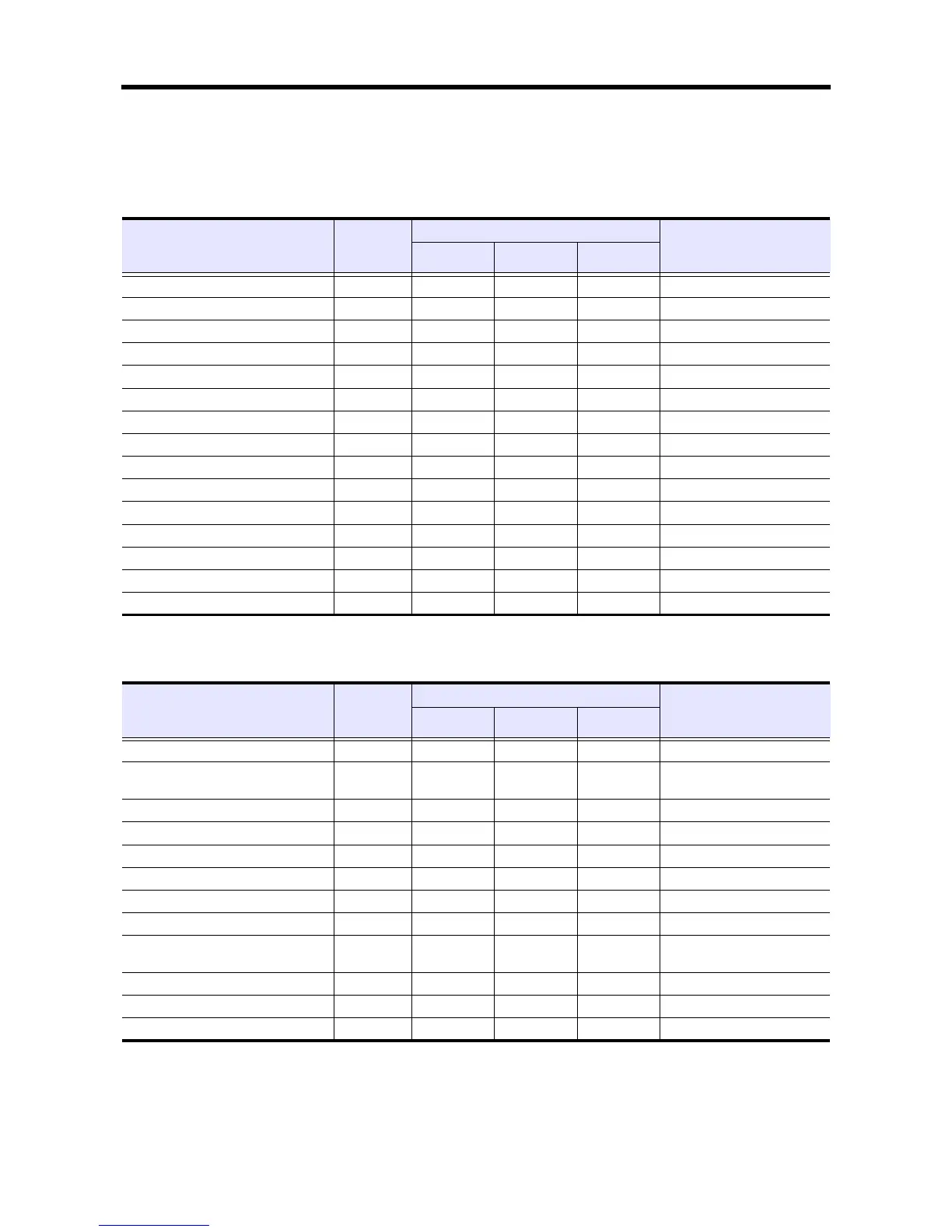
2. Tightening torque table
2.1 Major bolt tightening torque
2.1.1 Basic engine
2.1.2 Fuel system
Table 2-7 Tightening torque table - Basic engine
Description
Threads
Dia × Pitch
(mm)
Torque
Remark
N·m kgf·m lbf·ft
Cylinder head bolt 12 × 1.75 118 ± 5 12 ± 0.5 87 ± 3.6
Cylinder head plug 16 × 1.5 44 ± 5 4.5 ± 0.5 33 ± 3.6
Rocker cover 8 × 1.25 12 ± 1 1.2 ± 0.1 9 ± 0.7
Adjusting screw nut 8 × 1.25 20 ± 2 2 ± 0.2 14 ± 1.4
Rocker shaft bracket (short) 8 × 1.25 11.3 ± 1.5 1.15 ± 0.15 8 ± 1.1
Rocker shaft bracket (long) 8 × 1.25 15 ± 2 1.5 ± 0.2 11 ± 1.4
Main bearing cap 12 × 1.75 83 ± 5 8.5 ± 0.5 61 ± 3.6
Connecting rod cap 10 × 1.0 54 ± 5 5.5 ± 0.5 40 ± 3.6
Flywheel 12 × 1.25 83 ± 5 8.5 ± 0.5 61 ± 3.6
Camshaft thrust plate 8 × 1.25 12 ± 1 1.2 ± 0.1 9 ± 0.7
Front plate 8 × 1.25 12 ± 1 1.2 ± 0.1 9 ± 0.7
Timing gear case cover 8 × 1.25 12 ± 1 1.2 ± 0.1 9 ± 0.7
Crankshaft pulley 24 × 1.5 392 ± 10 40 ± 1 289 ± 7.2
Flywheel housing 10 × 1.25 60 ± 6 6.1 ± 0.6 44 ± 4.3
Rear plate stud 10 × 1.25 24 ± 2 2.4 ± 0.2 17 ± 1.4
Table 2-8 Tightening torque table - Fuel system
Description
Threads
Dia × Pitch
(mm)
Torque
Remark
N·m kgf·m lbf·ft
Fuel injection nozzle 20 × 1.5 59 ± 6 6 ± 0.6 43 ± 4.3
Fuel injection nozzle
retaining nut
16 × 0.75 36.8 ± 2.45 3.75 ± 0.25 27 ± 1.8
Fuel leak off pipe mounting nut 12 × 1.5 23 ± 2 2.3 ± 0.2 17 ± 1.4
Fuel injection pump gear 12 × 1.75 64 ± 5 6.5 ± 0.5 47 ± 3.6
Fuel injection pipe nut 12 × 1.5 29 ± 3 3 ± 0.3 22 ± 2.2
Fuel return pipe nut 10 × 1.25 20 ± 2 2 ± 0.2 14 ± 1.4
Fuel injection pump fuel eye bolt 14 × 1.5 17 ± 2 1.75 ± 0.2 13 ± 1.4
Fuel injection pump overflow valve 12 × 1.5 17 ± 2 1.75 ± 0.2 13 ± 1.4
Fuel injection pump lubrication pipe
(flare)
12 × 1.0 19 ± 3 1.95 ± 0.3 14 ± 2.2
Fuel injection pump lubrication connector R1/8 25 ± 2 2.5 ± 0.2 18 ± 1.4
Fuel injection pump lubrication eye bolt 10 × 1.0 10 ± 2.5 1.05 ± 0.2 8 ± 1.8
Separate oil filter connector 20 × 1.5 29 ± 5 3 ± 0.5 22 ± 3.6
 Loading...