DS
+
-
J
N
L
CC
11
9
7
3
1
5
Option
XR1
XR2
XR3
XR4
XR5
CNE CNFCNM
CNX
CNY
CNT
CNG
SM
LM1
LM2
Heat
HA
J
RD
Y/GN
G
Y/GN
BK
2/N
1
WH
3
2/N
1
3
L
N
RD
Y/GN
BK
R/LS/N
WH
WH
RD
BK
1
3
Y
BL
4
5
6
exchanger
ZNR
ZNR
F
250V
3.15A
F
250V
3.15A
Terminal block
TB TB
XZ
Y
XZ
Y
RD
WH
BK
BK
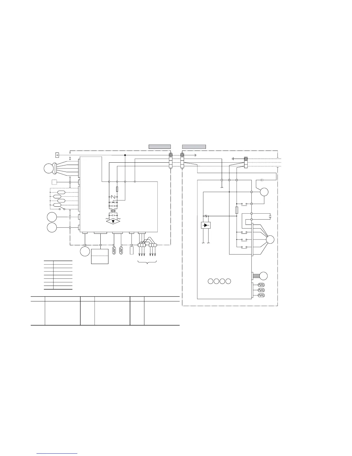
Color symbol
Meaning of marks
Symbol
CM
F
FM
I
FM
O
SM
LM
1,2
Th
1
Th
2
Compressor motor
Fuse
Fan motor(Indoor)
Fan motor(Outdoor)
Flap motor
Louver motor
Room temp.sensor
Heat exch.sensor(Indoor unit)
Capacitor for CM
Capacitor for FM
O
Terminal block
Operation indication (DC12)
Heating indication (DC12)
ON indication for CM(DC12)
Check indication (DC12)
Distant operation
Humidity sensor
Heat exch.sensor(Outdoor unit)
Outdoor air temp.sensor
Discharge pipe temp.sensor
Varistor
Electronic expansion valve
Diode stack
Auxiliary relay
Th
3
Th
4
Th
5
Th
6
ZNR
EEV
DS
52
X1~5
CC
CF
O
TB
XR1
XR2
XR3
XR4
XR5
Parts name
BL
OR
Y/G
Black
Blue
Orange
Yellow/Green
WH White
RD Red
GR Green
Y Yellow
Parts name Parts nameSymbol Symbol
BK
WH
RD
WH
RD
WH
OR
Y
RD
BL
BK
WH
BK
Y
Y
CM2
CM1
W
V
U
52X1
52X3
52X4
52X5
Power Source
1 Phase
220V 50Hz
To wired
remote
control
(Option)
R-AMP
Wireless
Display
board
Printed circuit
Printed circuit
board
CNU
JEM-A
CNB
CNU
CNE
CNG
FM
I
CM
EEV
FMo
CF
O
52X
1
52X
3
52X
4
52X
5
Th4
Th5
Th6
Outdoor unit
Indoor unit
Th3Th2Th1
~~
 Loading...