Managing the Wireless WallPlates
Motorola, Inc. 570510-001-00 rev A Page 26 of 50
M
M
a
a
n
n
a
a
g
g
i
i
n
n
g
g
t
t
h
h
e
e
W
W
i
i
r
r
e
e
l
l
e
e
s
s
s
s
W
W
a
a
l
l
l
l
P
P
l
l
a
a
t
t
e
e
s
s
The Wireless WallPlate is managed through two interfaces; one interface is via an embedded management
channel within the VDSL frames. The other interface is through a layer 3 IP address.
W
W
a
a
l
l
l
l
P
P
l
l
a
a
t
t
e
e
I
I
n
n
v
v
e
e
n
n
t
t
o
o
r
r
y
y
a
a
n
n
d
d
F
F
i
i
r
r
m
m
w
w
a
a
r
r
e
e
I
I
m
m
a
a
g
g
e
e
Show remote inventory
“show remote inventory” command uses the embedded channel to read hardware rev and basic information,
including serial number and BSS MAC range. Additionally, this out-of-band channel is used to detect the device
and initiate communications. This interface can operate if IP addressing is invalid or the system is unable to
communicate at Layer 3. This command will read hardware information for the Wireless WallPlate or the m2
Ethernet WallPlate.
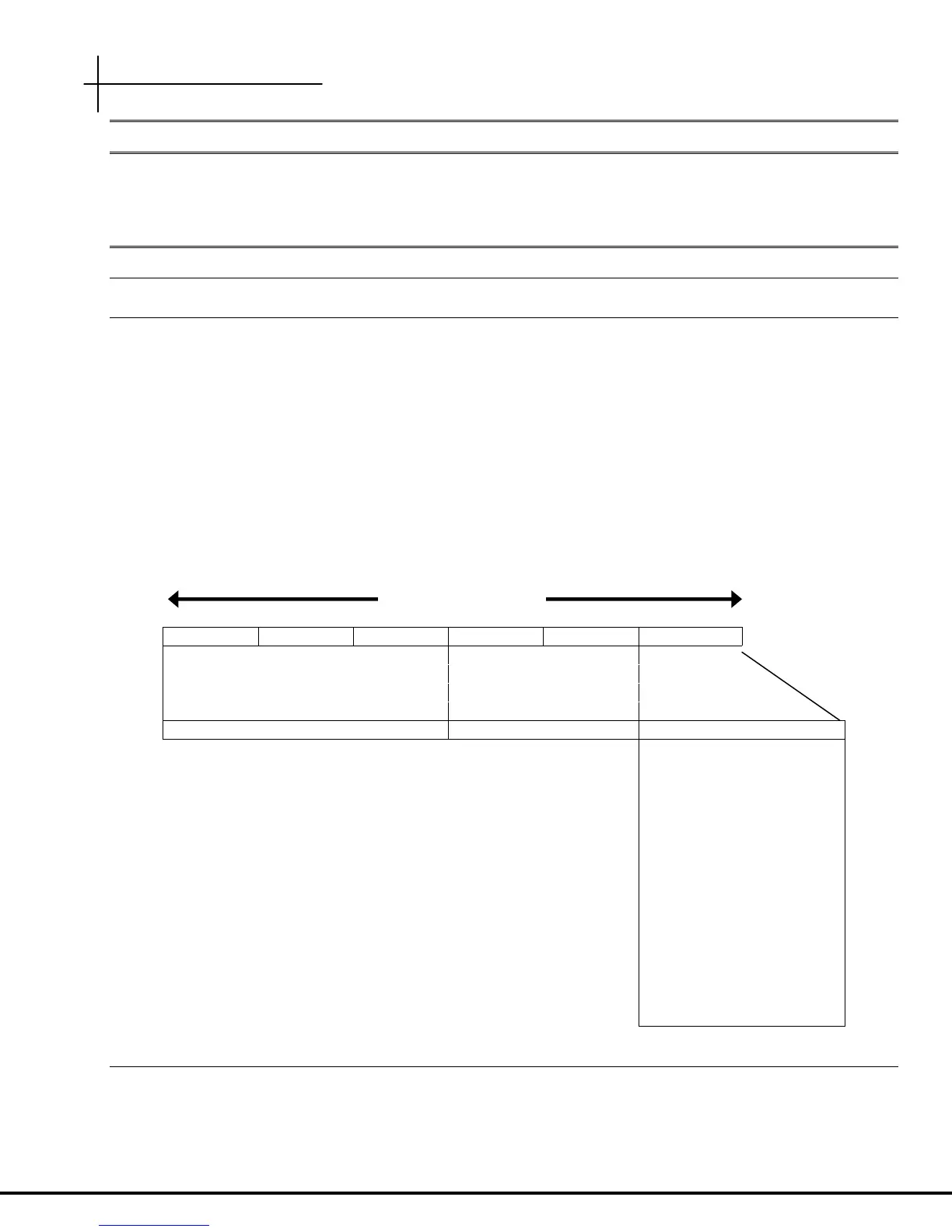
Each Wireless WallPlate has 16 MACs, assigned to 16 WLANs. To read the MAC addresses assigned to the
WLANs, use;
show remote inventory port<x>
Note that only one MAC address is shown for the BSS. This is the starting MAC, assigned to WLAN 1 on that
radio. The remaining 15 WLANs will increment from the last octet, 00.
00 C0 23 xx xx x0
3-byte vendor ID 2-byte device ID 1-byte device ID
00 = WLAN 1
01 = WLAN 2
02 = WLAN 3
03 = WLAN 4
04 = WLAN 5
05 = WLAN 6
06 = WLAN 7
07 = WLAN 8
08 = WLAN 9
09 = WLAN 10
0A = WLAN 11
0B = WLAN 12
0C = WLAN 13
0D = WLAN 14
0E = WLAN 15
0F = WLAN 16
Show remote image
“show remote image” command uses the layer 3 interface to communicate. Use this command to ensure the
T3 has full access to the Wireless WallPlate. Note this command will not read information from an m2 Ethernet
WallPlate. If this command stalls, then the T3 cannot communicate. This is most likely an IP addressing mistake.
6 b
te MAC address
 Loading...