EasyManuals Logo
Home>Motorola>Cordless Telephone>549478-001-00 - PowerBroadband EthernetXD M2a WallPlate Switch

Motorola 549478-001-00 - PowerBroadband EthernetXD M2a WallPlate Switch User Manual

Motorola 549478-001-00 - PowerBroadband EthernetXD M2a WallPlate Switch
50 pages
To Next Page IconTo Next Page
To Previous Page IconTo Previous Page
Page #35 background imageLoading...
Page #35 background image
RADIUS network authenticated login
Motorola, Inc. 570510-001-00 rev A Page 35 of 50
Step 2
Connect 50mm (2”) cable (supplied) between bottom mounted RJ11 port on the MC-802 and the existing RJ11 jack.
Step 3
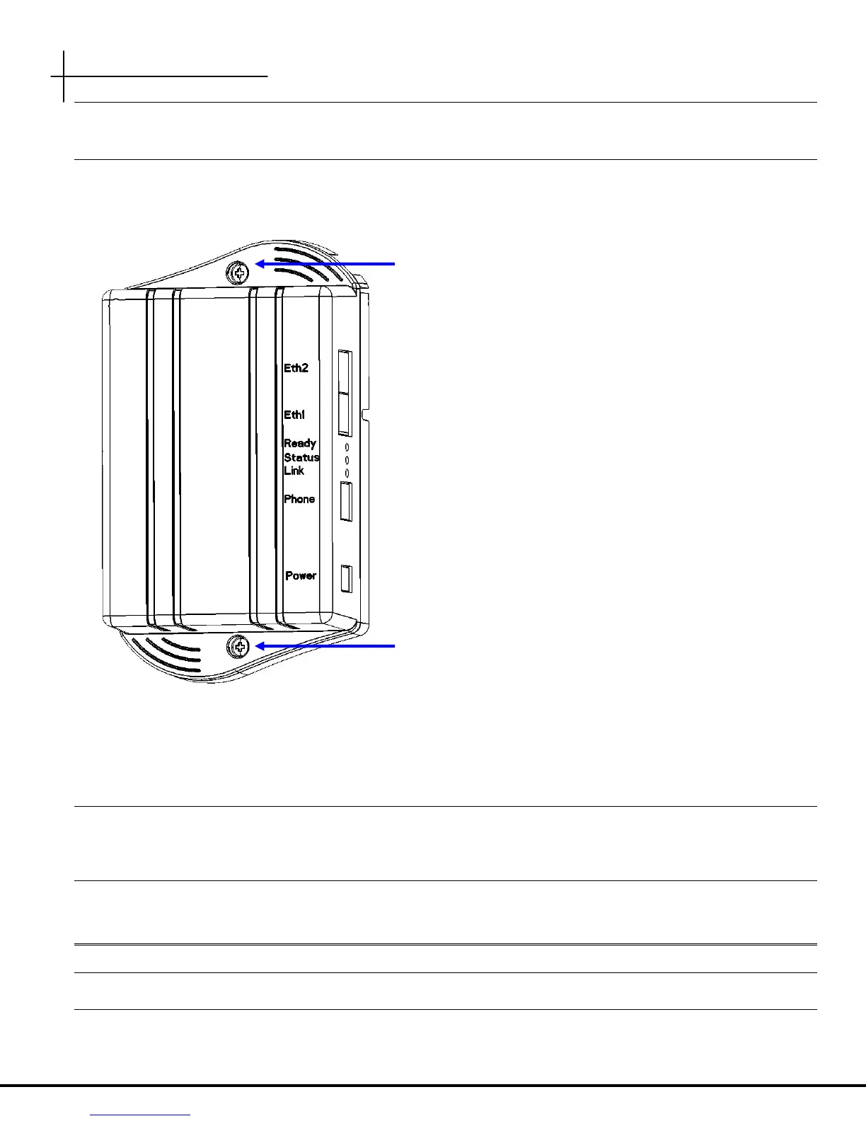
Attach the MC-802 to the Mounting Adapter using the supplied 6/32 thread forming screws
Step 4
1. Connect the local AC power adapter to the WallPlate
2. Connect the analog phone to the RJ11 phone jack
Step 5
After WallPlate Link LED is solid, verify the device is connected using the command, “show int dsl status”. It is best to
have a technician in the phone room directly connected to the T3 Switch to coordinate and enable Line Power.
E
E
n
n
a
a
b
b
l
l
e
e
l
l
i
i
n
n
e
e
p
p
o
o
w
w
e
e
r
r
Determine which port is being installed
From the CLI, enter this command:
6/32 thread forming screws

Other manuals for Motorola 549478-001-00 - PowerBroadband EthernetXD M2a WallPlate Switch

Questions and Answers:

Question and Answer IconNeed help?

Do you have a question about the Motorola 549478-001-00 - PowerBroadband EthernetXD M2a WallPlate Switch and is the answer not in the manual?

Motorola 549478-001-00 - PowerBroadband EthernetXD M2a WallPlate Switch Specifications

General IconGeneral
BrandMotorola
Model549478-001-00 - PowerBroadband EthernetXD M2a WallPlate Switch
CategoryCordless Telephone
LanguageEnglish

Related product manuals