Transmit Signalling Circuits
6.3-10 Theory of Operation
5.0 Transmit Signalling Circuits
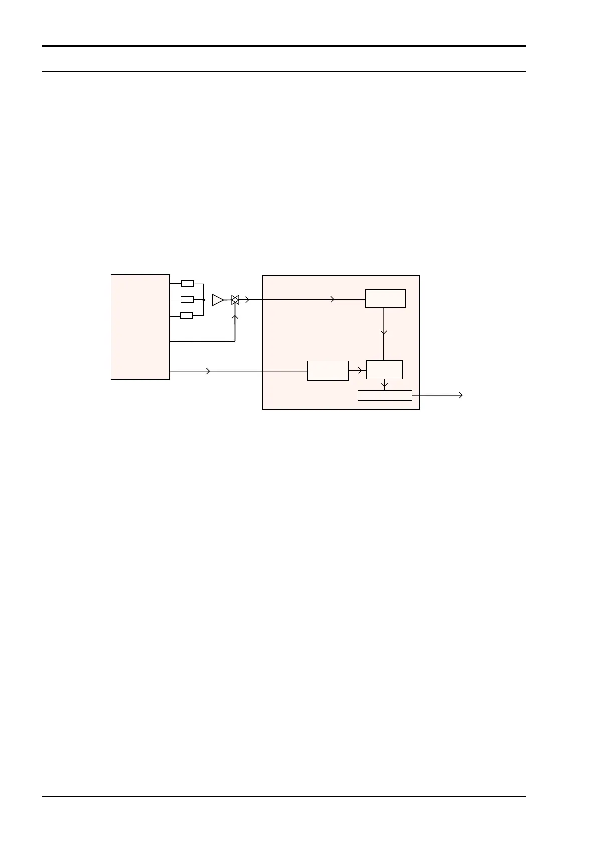
Refer to Figure 6.3-2 for reference for the following sections. From a hardware point of view, there
are three types of signalling:
1. Sub-audible data (PL / DPL / Connect Tone) that gets summed with transmit voice or signal-
ling,
2. DTMF data for telephone communication in trunked and conventional systems, and
3. Audible signalling including Select 5, MPT-1327, MDC, Single Tones.
All three types are supported by the hardware while the radio software determines which signalling
type is available. Currently only PL/DPL and Single tones are supported in the software.
Figure 6.3-2 Transmit Signalling Paths
5.1 Sub-audible Data (PL/DPL)
Sub-audible data implies signalling whose frequency is below 300Hz. Although it is referred to as
”sub-audible data,” the actual frequency spectrum of these waveforms may be as high as 250 Hz,
which is audible to the human ear. However, the radio receiver filters out any audio below 300Hz, so
these tones are never heard in the actual system.
Only one type of sub-audible data can be generated by U0103 (AFIC) at any one time. The process
is as follows, using the SPI BUS, the µP programs the AFIC to set up the proper low-speed data
deviation and select the PL or DPL filters. The µP then generates a square wave which strobes the
AFIC PL / DPL encode input PL CLOCK STROBE U0103-32 at twelve times the desired data rate.
For example, for a PL frequency of 103Hz, the frequency of the square wave would be 1236Hz.
This drives a tone generator inside U0103 which generates a staircase approximation to a PL sine
wave or DPL data pattern. This internal waveform is then low-pass filtered and summed with voice
or data. The resulting summed waveform then appears on U0103-19,20 (MOD IN), where it is sent
to the RF board as previously described for transmit audio.
GEPD_5432
13
32
42
19, 20
MOD IN
TO RF
SECTION
(SYNTHESIZER)
GEPD 5432-1
57
58
54
AUX TX
IN
PL
CLOCK
STROBE
ASFIC U0201
MICRO
CONTROLLER
U0101
SPLATTER
FILTER
PL
ENCODER
LS
SUMMER
ATTENUATOR
62
http://www.myradio168.net
 Loading...


