Receive Signalling Circuits
Theory of Operation 6.3-15
7.0 Receive Signalling Circuits
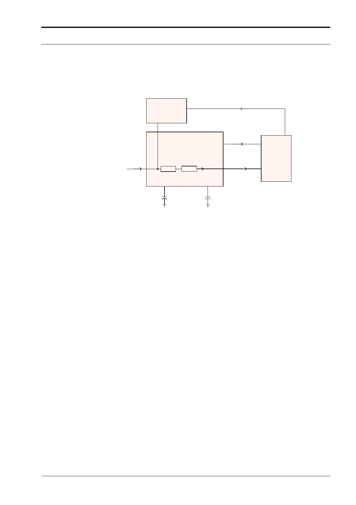
Refer to Figure 6.3-4 for reference for the following sections.
Figure 6.3-4 Receive Signalling Path.
7.1 Sub-audible Data Decoder (PL/DPL)
The receiver audio signal entering the AFIC U0103 at pin 8 first passes through the Tone PL filter or
the Digital PL filter, depending on the PL option selected for the current operating mode. Filtered PL
is then coupled to the PL detector circuit, with detected PL output at U0103-27. At this point the
signal will appear as a square wave version of the sub-audible signal which the radio received. The
microprocessor U0101-64 will decode the signal directly to determine if it is the tone / code which is
currently active on that mode.
7.2 High Speed Data Decoder
The unattenuated receiver audio signal from U0103-22 is AC coupled to the input of centre slicer
circuit U0105-2. The non-inverting input of Op-amp U0105-2 is fed through resistor R0162.
Capacitor C0164 sets a low-pass corner frequency of 3.3kHz. The inverting input of Op-amp U0105-
2 is fed through resistor R0163. Capacitor C0163 sets a low-pass corner frequency of 16Hz.
During operation, R0163 / C0163 establish an average DC offset level at U0105-2 pin 6 dependent
on the average DC level of the undetected signal to set the “trigger” threshold of U0105-2. R0162 /
C0164 provide high audio frequency roll-off to improve falsing immunity, but passes 600 or 1200
baud signals. The detected output from the centre slicer circuit is buffered and inverted by Q0161
and then coupled to the µP U0101-1 where algorithms perform the final decoding.
GEPD_5430
DET AUDIO
DISCRIMINATOR AUDIO
FROM RF SECTION
(IF IC)
27
GEPD 5430
25
24
22
32
8
57
1
64
HIGH SPEED DATA
CENTRE SLICER
U0105-2
PL CLOCK
STROBE
PL
DPL
IN
TPL
PL DPL
DECODER
OUT
AFIC
U0103
DPL
UNATTEN
RX OUT
MICRO
CONTROLLER
U0101
FILTER
LIMITER
http://www.myradio168.net
 Loading...


