Disassemble the Radio
3-2 Maintenance
1. Insert a small ßat blade screw driver in the side recess of the radio chassis.
2. Lift the top cover over the chassis.
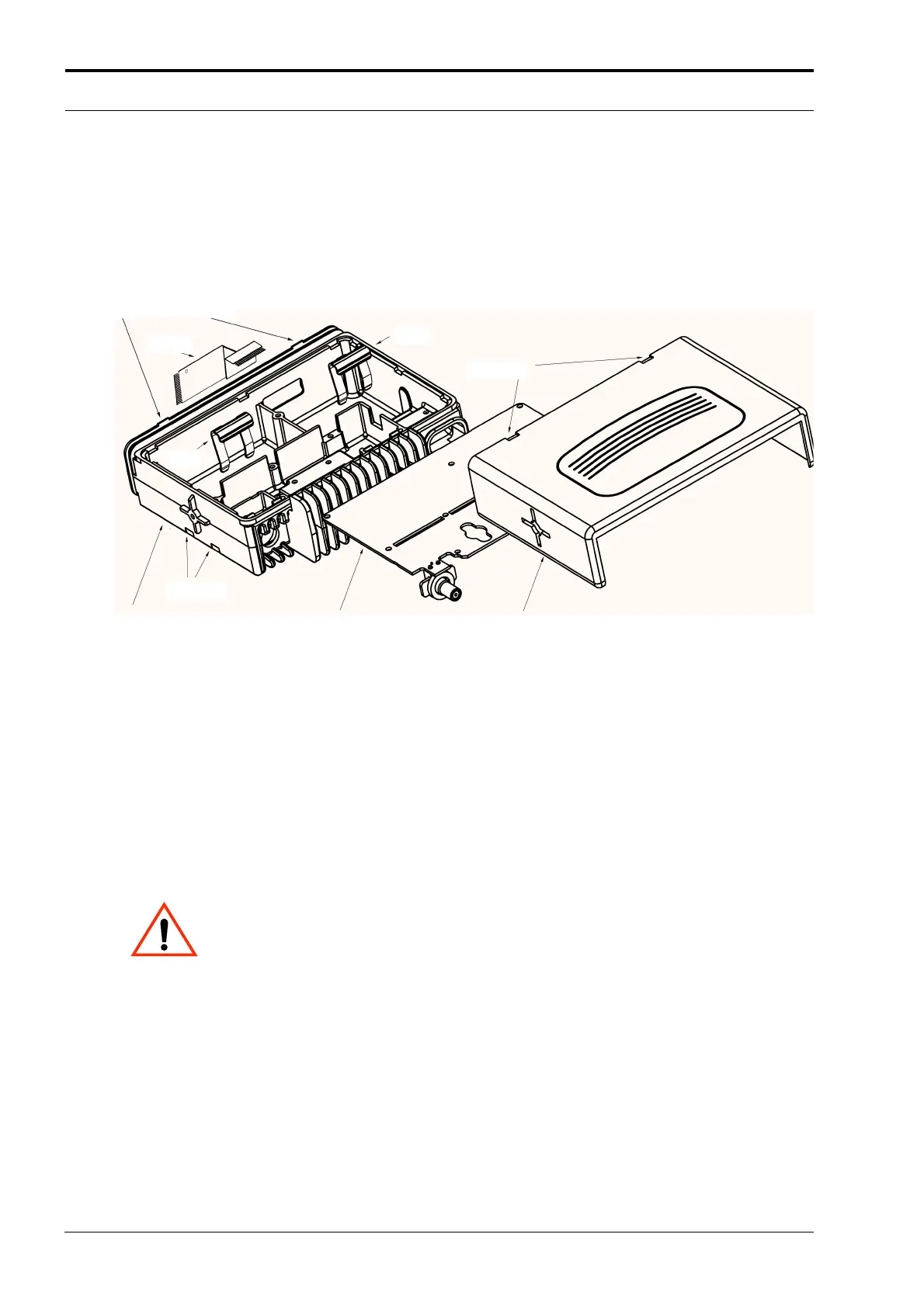
2.3 Remove the Transceiver Board
Figure 3-3 Transceiver Board Removal.
1. Remove the power and antenna connector retaining clips by inserting a small ßat blade screw
driver between the clip and the top of the chassis wall and gently prying the clip upwards.
2. Remove 13 screws from the transceiver board using a T8 TORX driver.
3. Carefully remove the transceiver board by rotating it out of the chassis:
Slowly lift the board on the front edge, the side with the connector that mates with the control
head, and pull gently toward the front of the radio.
CAUTION: The thermal grease can act as an adhesive and cause the leads of the
heat dissipating devises to be over stressed if the board is lifted too quickly.
2.4 Disassemble the Control Head
1. To pull out the printed circuit board from the control head housing, insert a small blade screw
driver in the side groove near the four protruding tabs. Remove the board from the control head
housing.
2. Disconnect the board from the speaker by removing from the socket.
3. Remove the keypad from the control head housing by lifting up the rubber keypad. Care should
be taken not to touch or get other contaminates on the conductive pads on the under side of
the keypad or conductive contacts on the printed circuit board.
Chassis
Recess
Top Cover
Flex
Printed Circuit Board
Chassis
Recess
Top Cover
Flex
Transceiver Board
Clip
Clip
Recess
Protruding Tabs
http://www.myradio168.net
 Loading...


