Assemble Radio
Maintenance 3-3
3.0 Assemble Radio
3.1 Assemble the Control Head
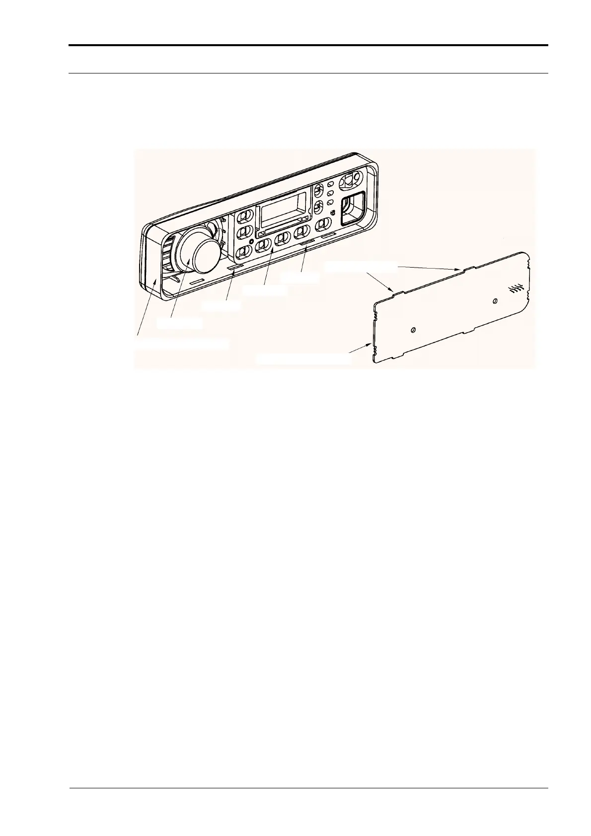
Figure 3-4 Control Head Assembly.
1. Place the keypad onto the board assembly, making sure the keypad is ßush with the board.
2. Make sure the speaker including the gasket is well positioned.
3. Connect the printed circuit board to the speaker.
4. During the installation of the printed circuit board, ensure the four protruding tabs snap into the
recesses.
3.2 Replace the Transceiver Board
1. Inspect and if necessary, reapply thermal grease to the heatsinking pads in the chassis.
2. Before installing the connector retaining clips, ensure that the board is sitting ßush on the
chassis mounting surface.
3. Install the 13 screws with 0.4 -07 NM (4-6 in lbs) of torque using a T8 TORX driver.
3.3 Replace the Top Cover and Control Head
1. Position the top cover over the chassis and replace. Ensure that the cross snaps into the
recesses.
2. Connect the control head to the radio by the ßex.
3. Press the control head onto the radio chassis until the protruding tabs on the chassis snap into
the recesses inside the control housing, see Figure 3-5.
Control Head Housing
Speaker
Recess
Keypad
Recess
Protuding Tabs
Printed Circuit Board
http://www.myradio168.net
 Loading...


