Transmitter 6D-3
3.0 Transmitter
3.1 General
(Refer to Figure 6-1)
The VHF transmitter contains five basic circuits:
1. power amplifier
2. antenna switch
3. harmonic filter
4. antenna matching network
5. power control integrated circuit (PCIC).
3.1.1 Power Amplifier
The power amplifier consists of two devices:
1. 9Z67 LDMOS driver IC (U101) and
2. PRF1507 LDMOS PA (Q110).
The 9Z67 LDMOS driver IC contains a 2 stage amplification with a supply voltage of 7.3V.
This RF power amplifier is capable of supplying an output power of 0.3W (pin 6 and 7) with an input
signal of 2mW (3dBm) (pin16). The current drain would typically be 160mA while operating in the
frequency range of 330-400MHz.
The PRF1507 LDMOS PA is capable of supplying an output power of 7W with an input signal of
0.3W. The current drain would typically be 1300mA while operating in the frequency range of 330-
400MHz. The power output can be varied by changing the biasing voltage.
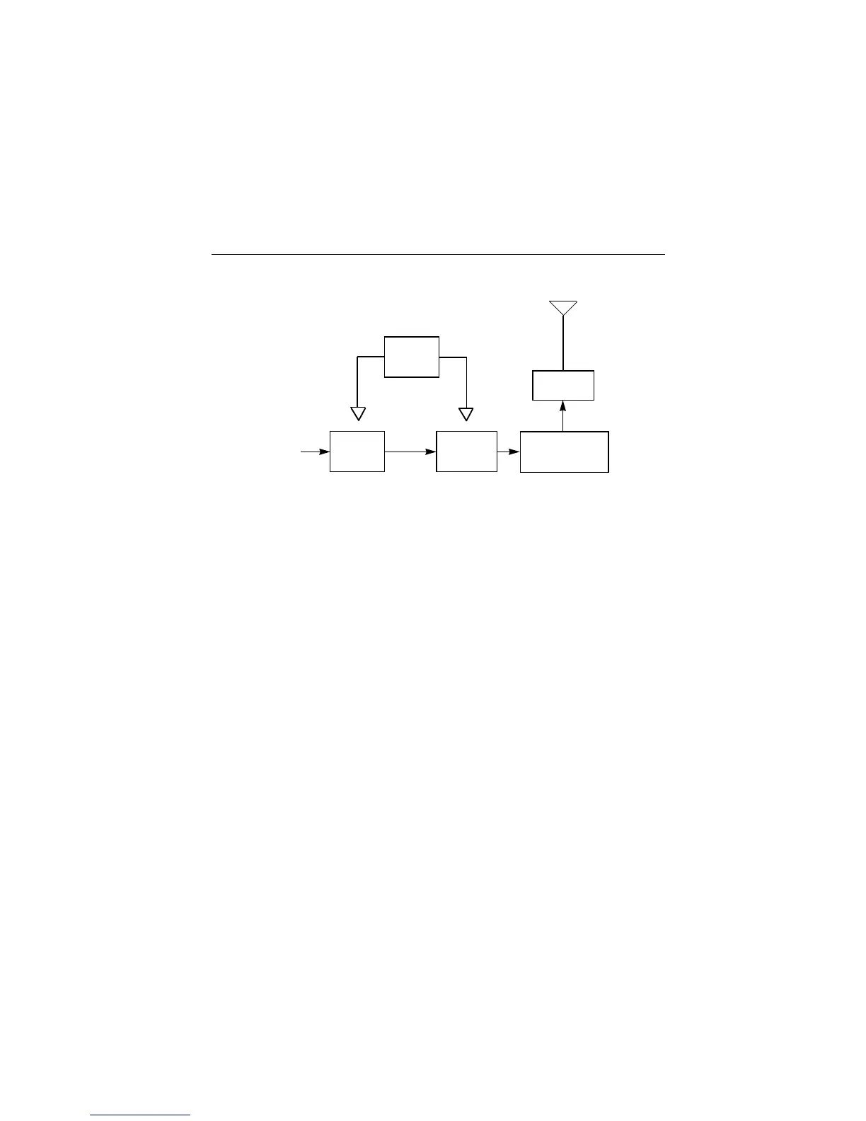
Figure 6-1: Transmitter Block Diagram
PCIC
Antenna
PA
Driver
Vcontrol
Vcontrol
From VCO
Jack
PA - F i n a l
Stage
Antenna Switch/
Harmonic Filter/
Matching Network

 Loading...


