4-2 Controller Board
When low battery level is detected by the microprocessor through both conditions above, it will store
the radio personality data to EEPROM before turning off.
3.0 Controller Board
3.1 General
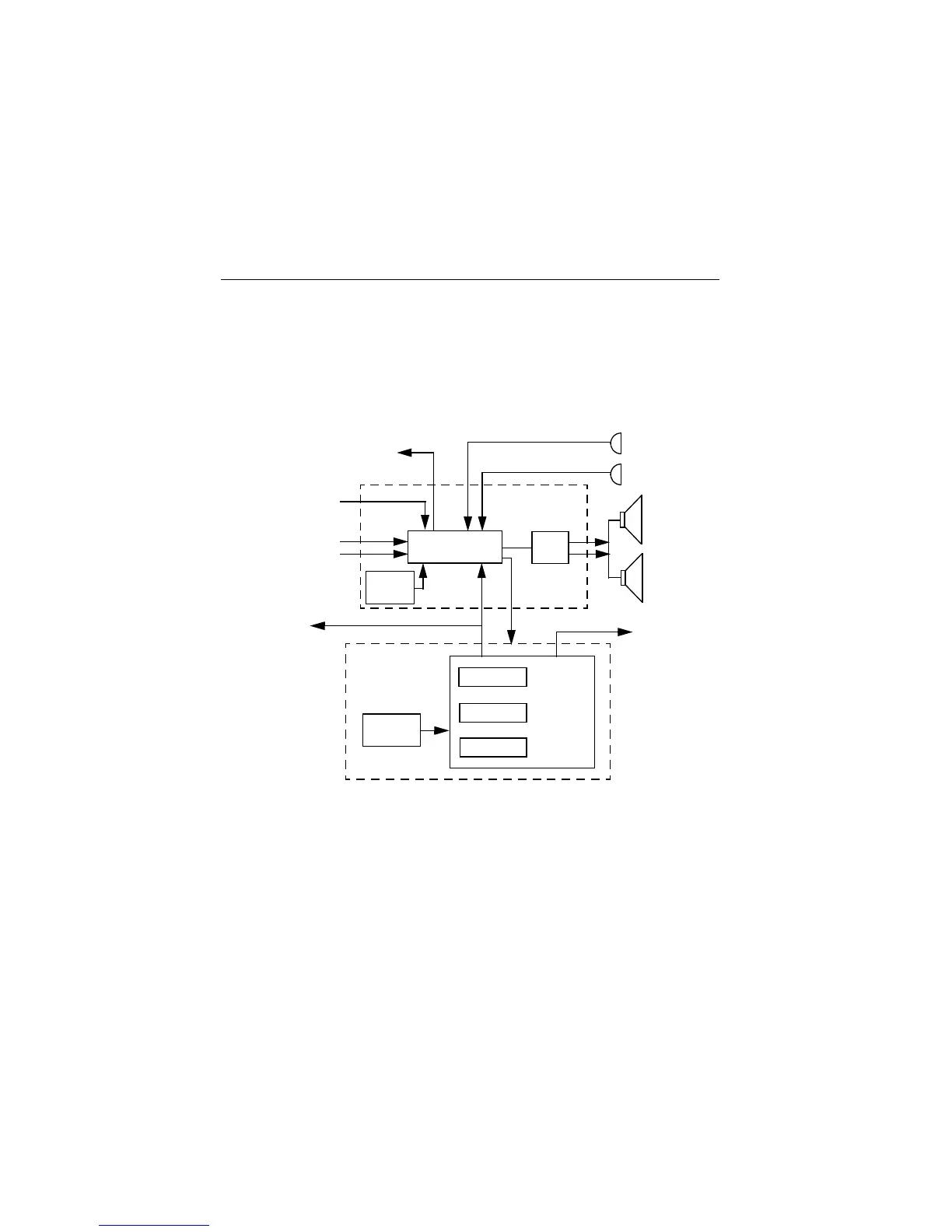
The controller board is the central interface between the various subsytems of the radio. It is
separated into digital and audio architectures. The digital portion consists of a special Motorola
microcontroller (HC11FL0). The audio power amplifier (Audio PA) and audio/signalling/filter/
companding IC (ASFIC_CMP) form the backbone of the audio/signalling architecture.
Figure 4-2: Controller Block Diagram
External
Microphone
Internal
Microphone
External
Speaker
Internal
Speaker
SCI to Side
Connector
Audio
PA
Audio/Signalling
Architecture
To Synthesizer
Mod
Out
16.8 MHz
Reference Clock
from Synthesizer
Recovered Audio
Squelch
To RF Board
SPI
Digital
Architecture
µPClock
3.3V
Regulator
(Vddd)
RAM
EEPROM
ROM
HC11FL0
ASFIC_CMP
3.3V
Regulator
(Vdda)

 Loading...


