Page 18
mrcool.com
4
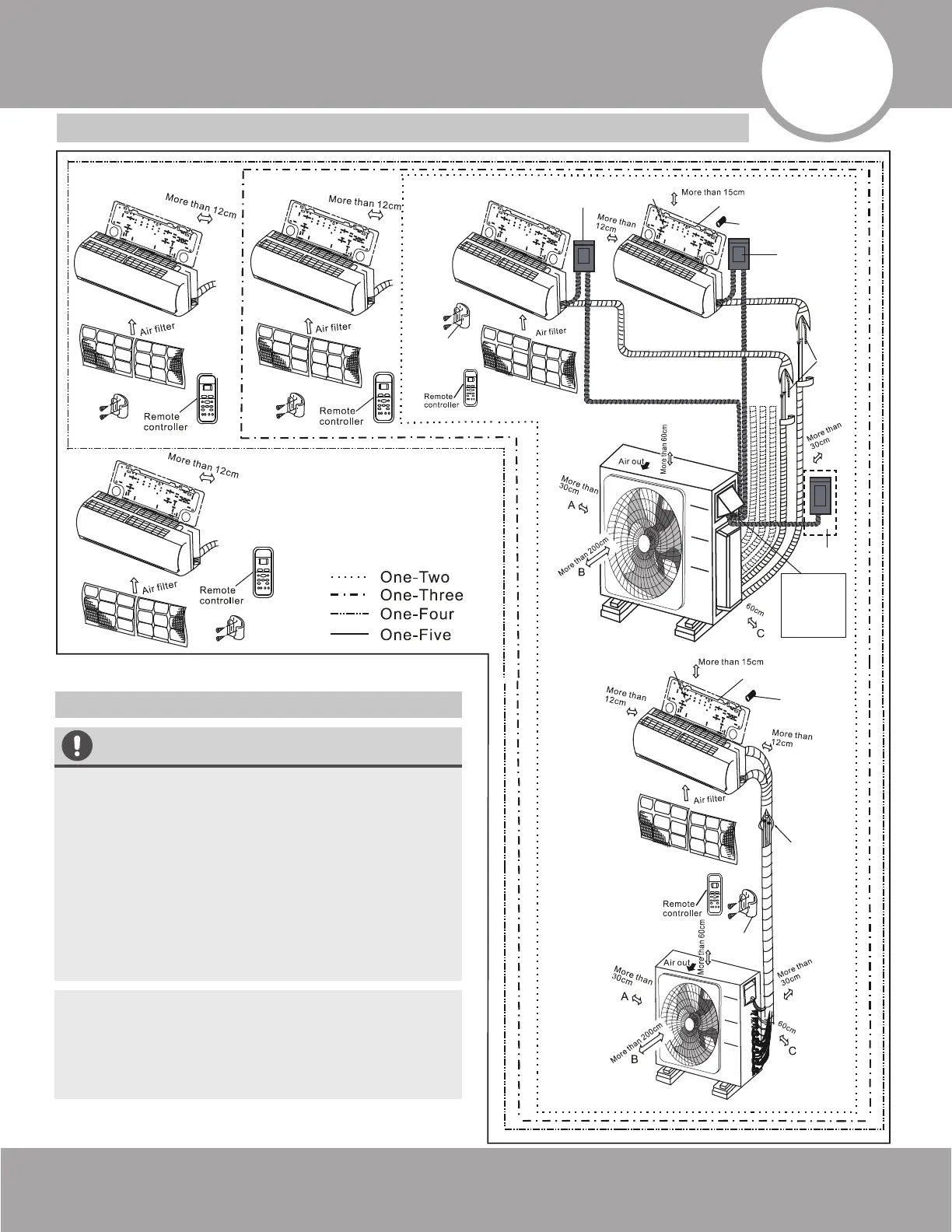
Installation Diagram &
Line Set Specifications
•
CAUTION
•
To prevent wall damage, use a stud finder to
locate studs to mount the units to.
A minimum pipe run of 9.8 ft (3 m) is required
to minimize vibration & excessive noise.
Two of the A, B, and C air circulation pathways
of the outdoor unit must be free from
obstructions at all times (Refer to illustration).
This illustration is for demonstration purposes
only. The actual shape and size of your air
conditioner may vary.
NOTE: The installation of this system must be
performed in accordance with the requirements
of local and national standards. These could be
different based on the region it is being
installed in.
•
•
Safety Precautions
Installation
plate
Mounting screw
ST3.9
×25-C-H
Refrigerant
pipe
Remote
controller
holder
Clip anchor
(2)
123
5
4
1
Installation plate
Mounting screw
ST3.9
×25-C-H
Clip anchor
(1)
Remote
controller
holder
5 4 3
2
The maximum
amount of the
connection
cables is 5. This
section is
for reference
only.
Air-break Switch
Drainage
Pipe
Air-break
Switch
Outdoor Unit
Power Cable
More than
More than
Fig. 4.1
Installation Diagram
 Loading...