Page 42mrcool.com
Refrigerant Piping Connection
Step 4: Connect Pipes
When connecting or bending refrigerant pipes, be
careful to avoid using excessive torque or deforming
the piping in any way. The low pressure piping should
be connected first, then the high pressure piping
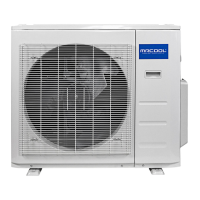
MINIMUM BEND RADIUS OF PIPING
When bending connective refrigerant piping,
the minimum bending radius is 4 in (10 cm).
Be sure not to dent or damage the piping
while bending it, as this could negatively
affect system performance. Please refer to
Fig. 7.6 below.
Minimum
Bend
Radius
Fig. 7.6
≥ 4 in
(10 cm)
REFRIGERANT PIPING FLARE DIMENSIONS & TORQUE REQUIREMENTS
Outer Diameter
of Pipe
Tightening
Torque
Flare
Dimension (B)
Flare Shape
Ø 0.25 in
(6.35 mm)
0.33~0.34 in
(8.4~8.7 mm)
0.52~0.53 in
(13.2~13.5 mm)
0.64~0.65 in
(16.2~16.5 mm)
0.76~0.78 in
(19.2~19.7 mm)
0.91~0.93 in
(23.2~23.7 mm)
13.28~14.75 ft•lb
(18~20 N•m)
23.60~28.76 ft•lb
(32~39 N•m)
36.14~43.52 ft•lb
(49~59 N•m)
42.04~52.37 ft•lb
(57~71 N•m)
49.42~74.49 ft•lb
(67~101 N•m)
Ø 0.375 in
(9.52 mm)
Ø 0.5 in
(12.7 mm)
Ø 0.63 in
(16 mm)
Ø 0.75 in
(19 mm)
R 0.4~0.8
45°
±
2
90°
± 4
B
Units: inch (millimeter), foot/pounds (newton meters)
DO NOT use excessive torque when tightening the flare nut. Excessive force can break the nut
or damage the refrigerant piping. You must not exceed the torque requirements shown in the
table below.
WARNING
Connection Instructions –
Refrigerant Piping
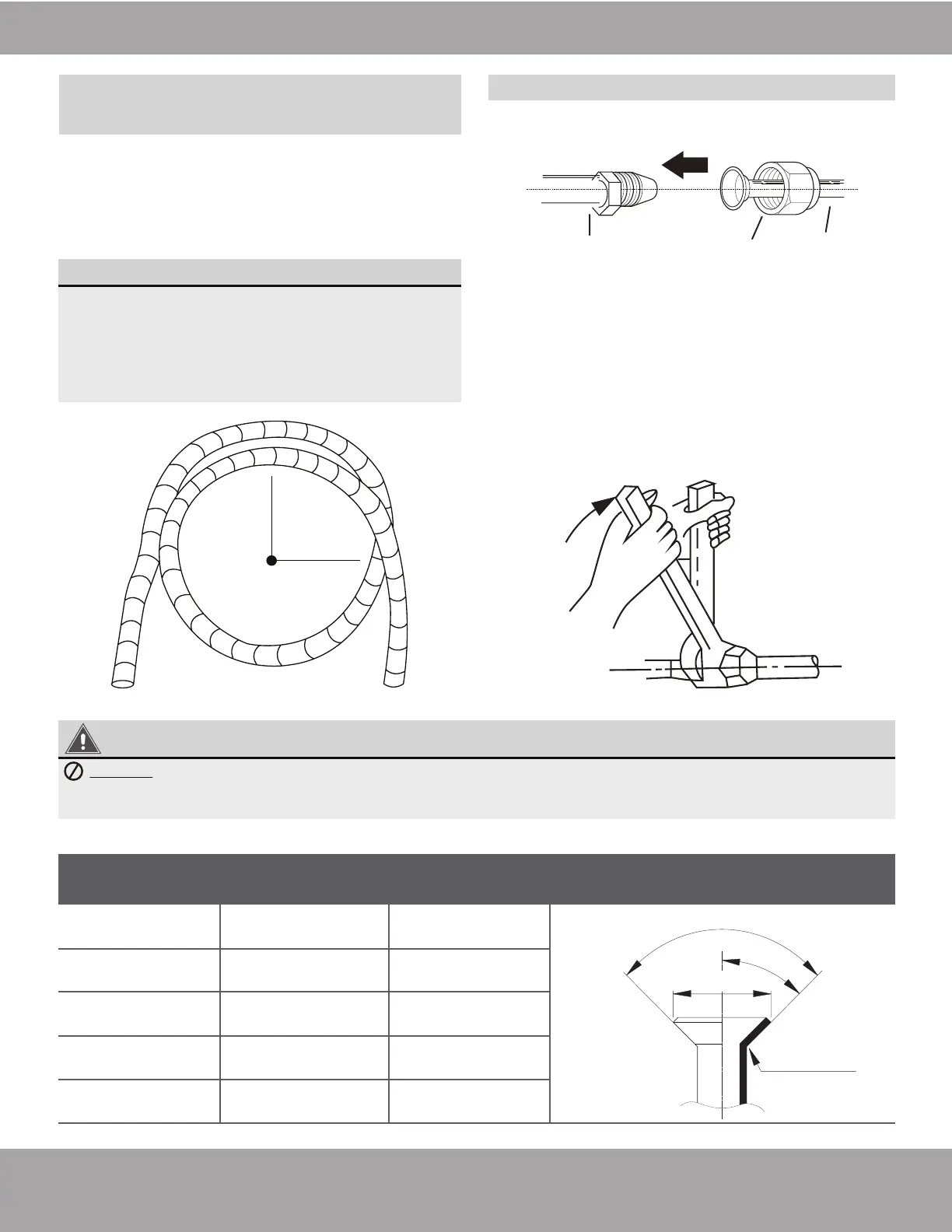
Connect Piping to Indoor Unit
1. Align the center of the two pipes to be connected.
Please refer to Fig. 7.7 below.
2. Tighten the flare nut as tightly as possible by hand.
3. Using a spanner, grip the nut on the indoor unit
tubing.
4. While firmly gripping the nut on the indoor unit
tubing with the spanner, use a torque wrench to
tighten the flare nut (Refer to Fig. 7.8 below).
Continue tightening the flare nut until the specified
torque rating in the table below (based on pipe
size) is achieved. Then, loosen the flare nut slightly
and tighten it again to the specified torque rating.
Indoor unit tubing Flare nut Pipe
Fig. 7.8
Fig. 7.7
 Loading...