Page 25 mrcool.com
Indoor Unit Installation
Wall
Indoor
Outdoor
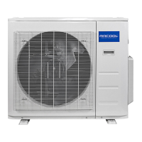
Fig. 5.4
0.2 - 0.3 in
(5 - 7 mm)
Drill used to
create wall
hole
1.
2.
3.
CAUTION
When drilling the wall hole, be sure to avoid
wires, plumbing, nails, screws, and other
sensitive components.
Step 3: Drill Wall Hole for Connective Piping
If refrigerant piping is not already embedded, you
must drill a hole in the wall for the refrigerant piping,
drainage pipe, and signal cable to pass through in
order to connect the indoor and outdoor units.
Determine the location of the wall hole based on
the position of the mounting plate. Refer to the
Mounting Plate Dimensions (Fig 5.3) to assist
you in determining the optimal position for the
hole, based on the type of mounting plate
provided with your unit.
Using a core drill, with a 2.5 in (65 mm) or 3.54 in
(90 mm) diameter (depending on model), drill a
hole in the wall at a slight downward angle, so
that the indoor end of the hole is higher than the
outdoor end of the hole, by approximately 0.2 in
to 0.275 in (5 mm to 7 mm). This will ensure
proper water drainage from the indoor unit (See
Fig. 5.4).
Insert the protective wall sleeve through the hole
of the inside wall. This will protect the edges of the
hole and help seal it when you finish the
installation process.
NOTE: If the system requires gas piping that
has diameter of 5/8 in (16 mm) or greater, the
wall hole size should be 3.54 in (90 mm).
Step 4: Prepare Indoor Unit Piping
The piping of the indoor unit is attached to the back
of the unit towards the bottom. It will be covered with
an insulation sleeve. You must prepare the piping
before the unit can be mounted and connected.
1.
2.
Based on the position of the wall hole (relative to
the mounting plate), or the location of the
embedded refrigerant piping, choose the side from
which the piping will exit the unit.
If the wall hole is behind the unit, keep the
knockout panel, as shown in the illustration below,
in place (Refer to Fig. 5.5). If the wall hole is to the
side of the indoor unit, remove the knockout panel
from that side of the indoor unit. This will create a
slot through which your piping can exit the unit. It
may be necessary to remove the knockout panel
with needle-nose pliers if it is too difficult to
remove by hand.
Correct Angle to Drill Wall Hole
3.
Use scissors to cut down the length of the piping
insulating sleeve to reveal roughly 1.57 in (40 mm)
of the refrigerant piping. This serves two purposes:
to facilitate the refrigerant piping connection
process, and allow the leak checks of the piping.
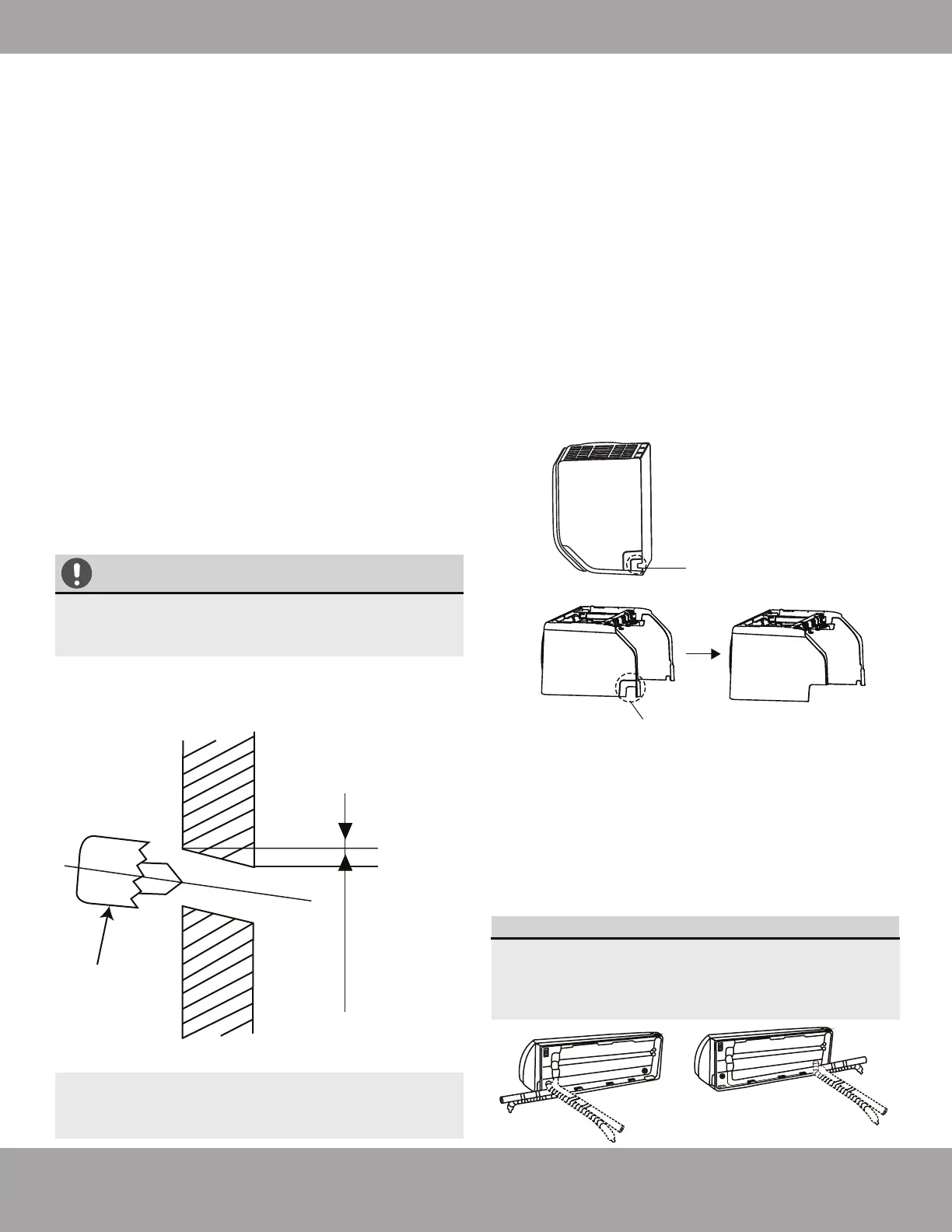
NOTE ON INDOOR UNIT PIPING ANGLE:
The refrigerant piping can exit the indoor unit
from four different angles: left-hand side, left
rear, right-hand side, and right rear. Refer to
Fig. 5.6 below for more details.
Fig. 5.6
Small knock-out panel
(cut depending on the
actual size needed)
If your installation requires a larger slot for the
piping to pass through cut out the larger panel
as shown above.
Fig. 5.5
 Loading...