2-19
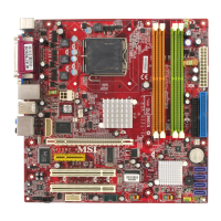
Hardware Setup
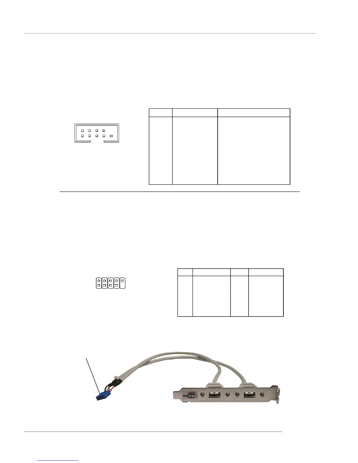
Connected to JUSB1
or JUSB2
USB 2.0 Bracket
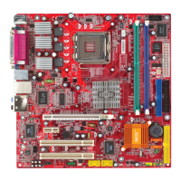
Front USB Connectors: JUSB1 & JUSB2
The mainboard provides two standard USB 2.0 pin headers JUSB1 & JUSB2 .
USB 2.0 technology increases data transfer rate up to a maximum throughput of
480Mbps, which is 40 times faster than USB 1.1, and is ideal for connecting high-
speed USB interface peripherals such as USB HDD, digital cameras, MP3 players,
printers, modems and the like.
PIN SIGNAL PIN SIGNAL
1 VCC 2 VCC
3 USB0- 4 USB1-
5 USB0+ 6 USB1+
7 GND 8 GND
9 Key (no pin) 10 USBOC
JUSB1 & JUSB2 Pin Definition
JUSB1, JUSB2
(USB 2.0)
Pin Definition
Serial Port Connector: JCOM2
The mainboard offers one serial port JCOM2. It is 16550A high speed communication
ports that senda/receivea/ 16 bytes FIFOs. You can attach a serial mouse or other
serial device directly to it.
JCOM2
PIN SIGNAL DESCRIPTION
1 DCD Data Carry Detect
2 SIN Serial In or Receive Data
3 SOUT Serial Out or Transmit Data
4 DTR Data Terminal Ready)
5 GND Ground
6 DSR Data Set Ready
7 RTS Request To Send
8 CTS Clear To Send
9 RI Ring Indicate
2
1
10
9
1
2
9
10
 Loading...