35
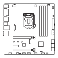
Overview of Components
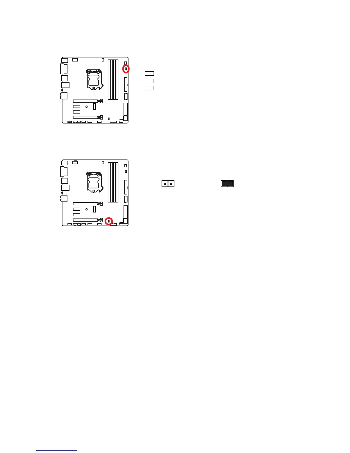
EZ Debug LED: Debug LED indicators
These LEDs indicate the status of the motherboard.
CPU - indicates CPU is not detected or fail.
DRAM - indicates DRAM is not detected or fail.
VGA - indicates GPU is not detected or fail.
JCI1: Chassis Intrusion Connector
This connector allows you to connect the chassis intrusion switch cable.
Normal
(default)
Trigger the chassis
intrusion event
Using chassis intrusion detector
1. Connect the JCI1 connector to the chassis intrusion switch/ sensor on the
chassis.
2. Close the chassis cover.
3. Go to BIOS > Settings > Security > Chassis Intrusion Configuration.
4. Set Chassis Intrusion to Enabled.
5. Press F10 to save and exit and then press the Enter key to select Yes.
6. Once the chassis cover is opened again, a warning message will be displayed on
screen when the computer is turned on.
Resetting the chassis intrusion warning
1. Go to BIOS > Settings > Security > Chassis Intrusion Configuration.
2. Set Chassis Intrusion to Reset.
3. Press F10 to save and exit and then press the Enter key to select Yes.
 Loading...