2-17
Hardware Setup
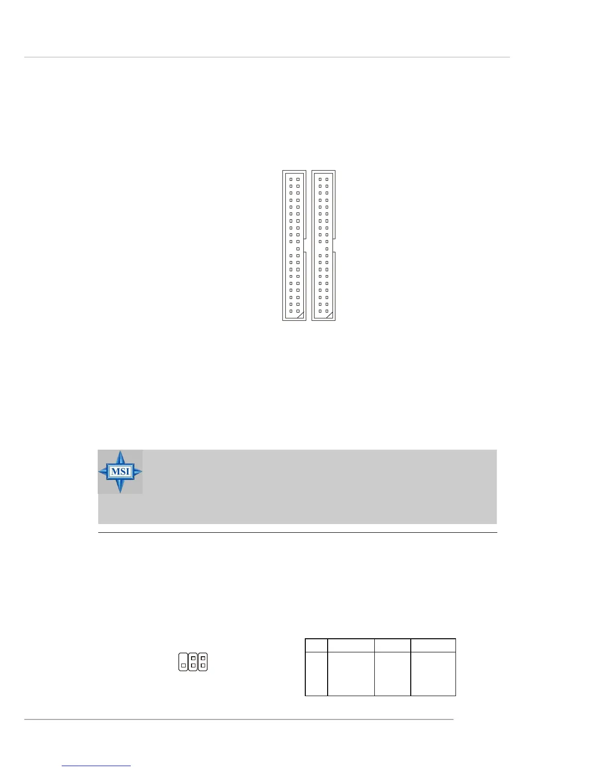
Hard Disk Connectors: IDE1/IDE2
The mainboard has a 32-bit IDE and Ultra DMA 33/66/100/133 controller that provides
PIO mode and DMA mode 0~5, Bus Master, and Ultra DMA 33/66/100/133 function.
You can connect up to four hard disk drives, CD-ROM, 120MB Floppy (reserved for
future BIOS) and other devices.
IDE1 (Primary IDE Connector)
The first hard drive should always be connected to IDE1. IDE1 can connect a Master
and a Slave drive. You must configure second hard drive to Slave mode by setting the
jumper accordingly.
IDE2 (Secondary IDE Connector)
IDE2 can also connect a Master and a Slave drive.
IDE2IDE1
MSI Reminds You...
If you install two hard disks on cable, you must configure the second
drive to Slave mode by setting its jumper. Refer to the hard disk
documentation supplied by hard disk vendors for jumper setting
instructions.
IrDA Infrared Module Header: JIR1
The connector allows you to connect to IrDA Infrared module. You must configure the
setting through the BIOS setup to use the IR function. JIR1 is compliant with Intel
®
Front Panel I/O Connectivity Design Guide.
JIR1 Pin Definition
Pin Signal Pin Signal
1NC 2 NC
3 VCC5 4 GND
5 IRTX 6 IRRX
JIR1
6
5
2
1
 Loading...