2-22
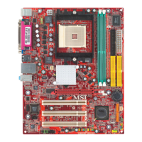
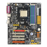
MS-6702E ATX Mainboard
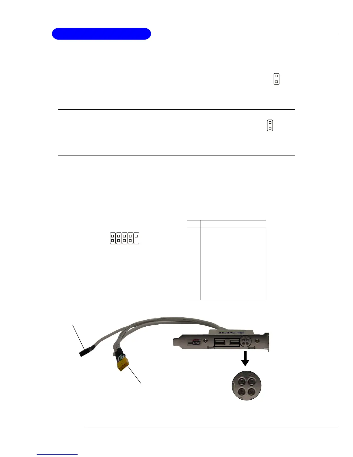
D-Bracket™ 2 Connector: JLED (Optional)
The mainboard comes with a JLED connector for you to connect to D-Bracket™ 2. D-
Bracket™ 2 is a USB Bracket that supports both USB1.1 & 2.0 spec. It integrates four
LEDs and allows users to identify system problem through 16 various combinations
of LED signals.
Pin Signal
1 DBG1 (high for green color)
2 DBR1 (high for red color)
3 DBG2 (high for green color)
4 DBR2 (high for red color)
5 DBG3 (high for green color)
6 DBR3 (high for red color)
7 DBG4 (high for green color)
8 DBR4 (high for red color)
9 Key
10 NC
JLED Pin Definition
JLED
1
9
2
10
D-Bracket™ 2
(Optional)
Connected to JUSB1 or JUSB2 (the
USB pinheader in YELLOW color)
Connected to JLED
LEDs
Chassis Intrusion Switch Connector: JCASE1
This connector is connected to a 2-pin chassis switch. If the chas-
sis is opened, the switch will be short. The system will record this
status and show a warning message on the screen. To clear the
warning, you must enter the BIOS utility and clear the record.
JCASE1
2
1
GND
CINTRU
Power Saving Switch Connector: JGS1
Attach a power saving switch to this connector. Press the switch
once to have the system entered the Sleep/Suspend state. Press
the switch again to wake up the system.
JGS1
 Loading...