Temposonics
®
E-Series
Brief Instructions
I 10 I
NOTICE
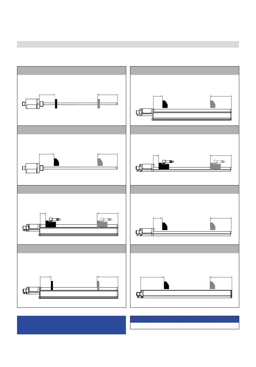
The mounting position of the sensor is arbitrary.
E-Series EH with ring- / U-magnet E-Series EP with block magnet
Start position
51 (2.01)
End position
63.5 (2.5)
Start position
32.5 (1.29)
End position
70.5 (2.78)
E-Series EH with block magnet E-Series EL with magnet slider “S” / “N” / “V” / “G”
Start position
48.5 (1.91)
End position
66 (2.6)
Start position
19 (0.75)
End position
84 (3.3)
E-Series EP with magnet slider “S” / “N” / “V” / “G” E-Series EL with block magnet
Start position
19 (0.75)
End position
84 (3.3)
Start position
32.5 (1.29)
End position
70.5 (2.78)
E-Series EP with U-magnet E-Series EP2 with block magnet
Start position
35 (1.38)
End position
68 (2.68)
Start position
73 (2.87)
End position
73 (2.87)
4.3 Mounting dimensions of E-Series
Controlling design dimensions are in millimeters and
measurements in ( ) are in inches
Manuals, Software & 3D Models
available at: www.mtssensors.com
Consider the start and end positions of the position magnets
during the installation. To ensure that the entire stroke length
is electrically usable, the position magnet must be mechanically
mounted as follows.

 Loading...