Temposonics
®
R-Series V PROFINET IO RT & IRT
Operation Manual
I 23 I
5. Operation
5.1 Initial start-up
The position sensor R-Series V PROFINET transfers position and
velocity values via the PROFINET output.
PROFINET was developed by the PROFIBUS & PROFINET International
(PI) organization and is a standard for transmissions in Industrial
Ethernet. The sensor and the corresponding GSDML file (General
Device Description) are certified by the Profibus Nutzerorganisation
e.V. (PNO).
The sensor can be ordered with different protocol options:
• MTS profile (U402/U412): The MTS profile was developed by MTS
Sensors for linear position sensors. With this profile, the position
and the velocity of up to 30 position magnets can be measured and
transferred simultaneously.
• Encoder profile (U401/U411): the encoder profile corresponds to
the specification of the encoder profile V4.2 (PNO no. 3.162). With
this profile, the position and the velocity of one position magnet can
be measured and transferred simultaneously.
The R-Series V PROFINET supports both RT mode and IRT mode.
With PROFINET RT (Real Time) the data exchange is without clock
synchronization. In this case, the application, the data transmission
and the field devices operate according to their own processing cycle.
With PROFINET IRT (Isochronous Real Time) a clock-synchronous
data transmission takes place. The application, the data transmission
as well as the device cycle are synchronous. IRT enables a clock-
synchronous data exchange with a minimum cycle time of 250s in
the network.
352),1(757,57/('VWDWXV
1
45
2
1
4
5
2
SE
S
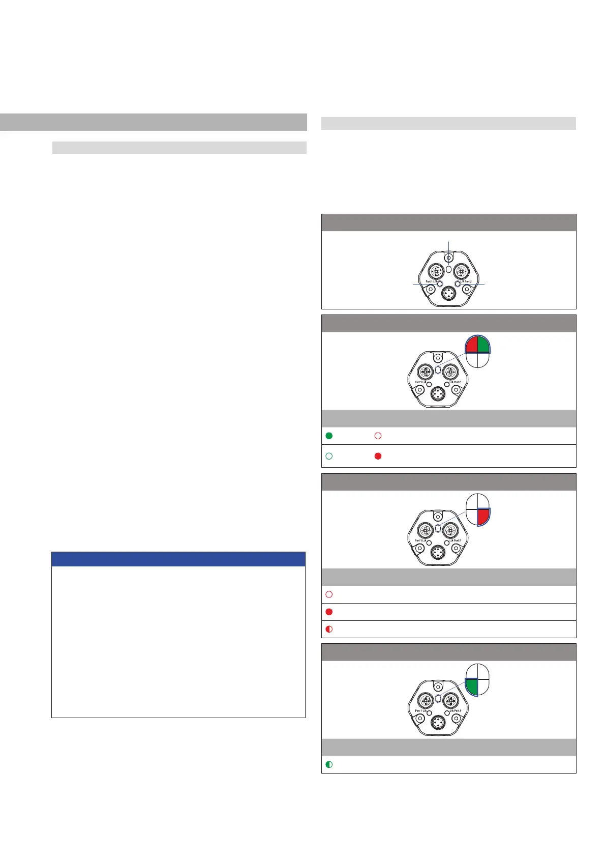
Connection indicator
Port 1 Port 2
i stats E
SE
S
1
45
2
1
45
2
rn d ,QIRUPDWLRQ
ON OFF
No error
OFF ON
Operating voltage out of range
or magnet error
s stats E
SE
S
1
45
2
1
45
2
d ,QIRUPDWLRQ
OFF No error
ON No connection to controller
Flashing Parameterization error
/('IRUVHQVRULGHQWLğFDWLRQ
SE
S
1
45
2
1
45
2
rn ,QIRUPDWLRQ
Flashing 6HQVRULGHQWLğFDWLRQDFWLYDWHG
5.2 LED Status
A diagnostic display on the lid of the sensor informs about the current
status of the sensor. The R-Series V is equipped with three LEDs:
• LED for status indication (condition indicator)
• LED for link activity of port 1 (port 1 L/A)
• LED for link activity of port 2 (port 2 L/A)
Fig. 29: LED status, part 1
NOTICE
Observe during commissioning
1. Before initial switch-on, check carefully if the sensor has been
connected correctly.
2. Position the magnet in the measuring range of the sensor during
fi rst commissioning and after replacement of the magnet.
3. Ensure that the sensor control system cannot react in an uncon-
trolled way when switching on.
4. Ensure that the sensor is ready and in operation mode after
switching on. The bus status LED is green.
5. Check the preset span start and end values of the measuring
range (see chapter 4.4) and correct them via the customer’s
control system, if necessary.
 Loading...


