Temposonics
®
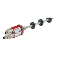
R-Series V PROFINET IO RT & IRT
Operation Manual
I 6 I
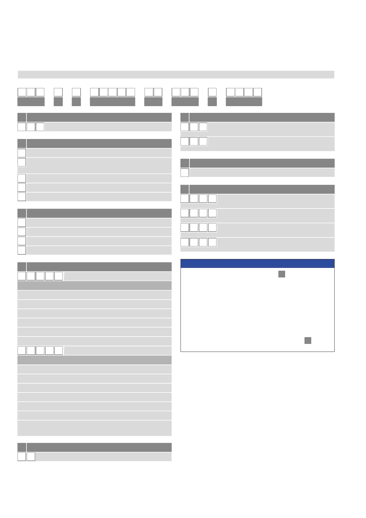
a Sensor model
R 5 Rod
b
Design
Base unit (only for replacement)
7KUHDGHGĠDQJH0ūJURGPP
stroke length: 25…5900 mm (1…232 in.)
M
7KUHDGHGĠDQJH0ūJVWDQGDUG
S
7KUHDGHGĠDQJHŧ81)$VWDQGDUG
7KUHDGHGĠDQJHŧ81)$ZLWKUDLVHGIDFH
c
Mechanical options
A Standard
Bushing on rod end (only for design »M«, »S« & »T«)
M Thread M4 at rod end (only for design »M«, »S« & »T«)
V Fluorelastomer seals for the sensor electronics housing
d Stroke length
X X X X M
0025…7620 mm
Standard stroke length (mm) Ordering steps
25… 500 mm
5 mm
500… 750 mm 10 mm
750…1000 mm 25 mm
1000…2500 mm 50 mm
2500…5000 mm 100 mm
5000
…
7620 mm 250 mm
X X X X
U
001.0…300.0 in.
Standard stroke length (in.) Ordering steps
1… 20 in.
0.2 in.
20… 30 in. 0.4 in.
30… 40 in. 1.0 in.
40…100 in. 2.0 in.
100…200 in. 4.0 in.
200…300 in. 10.0 in.
Non-standard stroke lengths are available;
must be encoded in 5 mm/0.1 in. increments.
.
e Number of magnets
X X
01…30 position(s) (1…30 magnet(s))
f Connection type
D 5 8
2 × M12 female connectors (D-coded),
1 × M12 male connector (A-coded)
D 5 6
2 × M12 female connectors (D-coded),
1 × M8 male connector
g System
1
Standard
h Output
U 4 0 2
PROFINET RT & IRT, position and velocity,
076SURğOHĽSRVLWLRQV
U 4 0 1
PROFINET RT & IRT, position and velocity,
HQFRGHUSURğOHSRVLWLRQ
U 4 1 2
PROFINET RT & IRT, position and velocity,
076SURğOHLQWHUQDOOLQHDUL]DWLRQĽSRVLWLRQV
U 4 1 1
PROFINET RT & IRT, position and velocity,
HQFRGHUSURğOHLQWHUQDOOLQHDUL]DWLRQSRVLWLRQ
NOTICE
• 6HOHFWWKH076SURğOH8RU8LQ
h
“Output” for multi-
position measurement.
• Specify the number of magnets for your application and order the
magnets separately.
• The number of magnets is limited by the stroke length.
The minimum allowed distance between magnets (i.e. front face
of one to the front face of the next one) is 75 mm (3 in.).
• Use magnets of the same type for multi-position measurement,
e.g. 2 × U-magnet (part no. 251 416-2).
• If the option for internal linearization (U411, U412) in
h
“Output”
is chosen, select a suitable magnet.
1 2 3 4 5 6 7 8 9 10 11 12 13 14 15 16 17 18 19 20
R 5
D 5 1
U 4
abc d e fg
h
3.2 Order code of Temposonics
®
RH5
 Loading...


