Temposonics
®
R-Series V PROFINET IO RT & IRT
Operation Manual
I 5 I
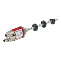
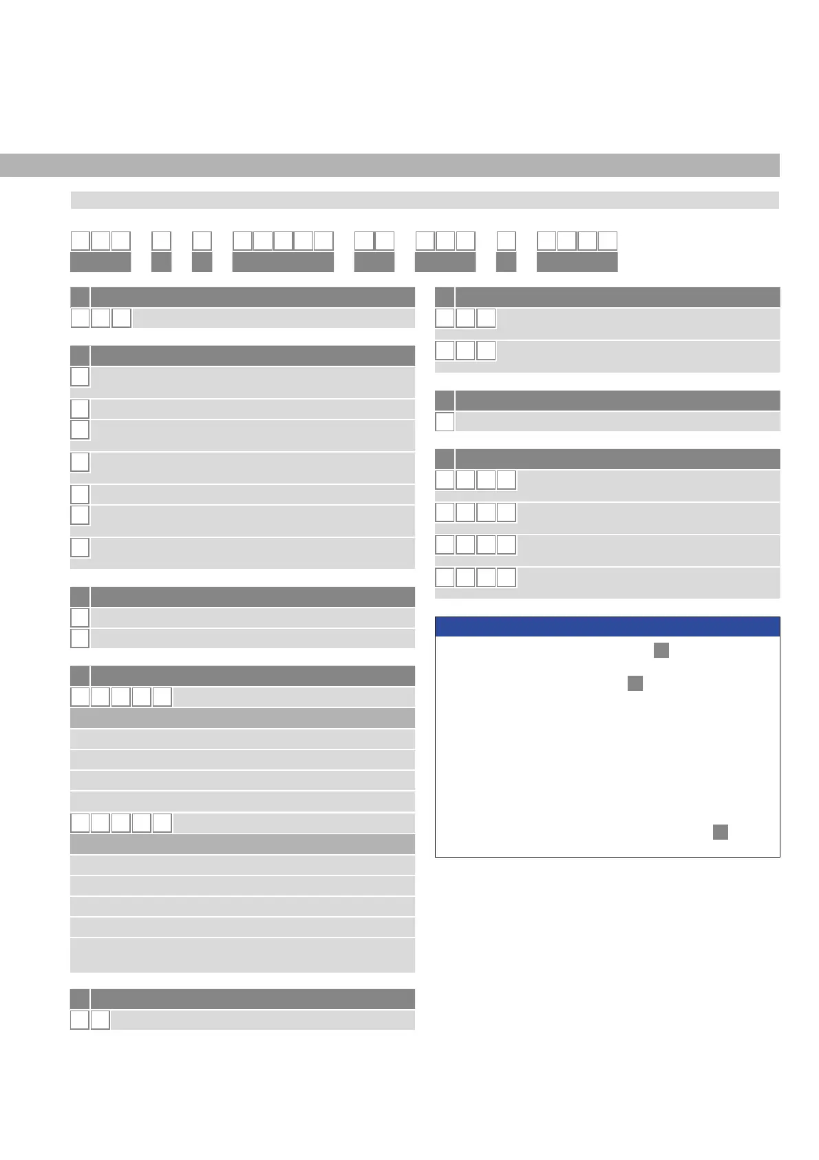
a Sensor model
R P
5
3URğOH
b Design
G
Magnet slider backlash free (part no. 253 421),
suitable for internal linearization
L
Block magnet L (part no. 403 448)
M
U-magnet OD33 (part no. 251 416-2),
suitable for internal linearization
N
Magnet slider longer ball-jointed arm (part no. 252 183),
suitable for internal linearization
O
No position magnet
S
Magnet slider joint at top (part no. 252
182),
suitable for internal linearization
V
Magnet slider joint at front (part no. 252
184),
suitable for internal linearization
c Mechanical options
A
Standard
V
Fluorelastomer seals for the sensor electronics housing
.
d Stroke length
X X X X M
0025…6350 mm
Standard stroke length (mm) Ordering steps
25… 500 mm 25 mm
500…2500 mm 50 mm
2500…5000 mm 100 mm
5000
…
6350 mm 250 mm
X X X X
U
001.0…250.0 in.
Standard stroke length (in.) Ordering steps
1… 20 in.
1.0 in.
20…100 in. 2.0 in.
100…200 in. 4.0 in.
200…250 in. 10.0 in.
Non-standard stroke lengths are available;
must be encoded in 5 mm/0.1 in. increments.
.
e Number of magnets
X X
01…30 position(s) (1…30 magnet(s))
f Connection type
D 5 8
2 × M12 female connectors (D-coded),
1 × M12 male connector (A-coded)
D 5 6
2 × M12 female connectors (D-coded),
1 × M8 male connector
g System
1
Standard
h Output
U
4
0 2
PROFINET RT & IRT, position and velocity,
076SURğOHĽSRVLWLRQV
U 4 0 1
PROFINET RT & IRT, position and velocity,
HQFRGHUSURğOHSRVLWLRQ
U 4 1 2
PROFINET RT & IRT, position and velocity,
076SURğOHLQWHUQDOOLQHDUL]DWLRQĽSRVLWLRQV
U 4 1 1
PROFINET RT & IRT, position and velocity,
HQFRGHUSURğOHLQWHUQDOOLQHDUL]DWLRQSRVLWLRQ
NOTICE
• 6HOHFWWKH076SURğOH8RU8LQ
h
“Output” for multi-
position measurement.
• For the RP5, the magnet selected in
b
“Design” is included in
the scope of delivery. Specify the number of magnets for your
application. For multi-position measurements with more than 1
magnet, order the other magnets separately.
• The number of magnets is limited by the stroke length.
The minimum allowed distance between magnets (i.e. front face
of one to the front face of the next one) is 75 mm (3 in.).
• Use magnets of the same type for multi-position measurement,
e.g. 2 × U-magnet (part no. 251 416-2).
• If the option for internal linearization (U411, U412) in
h
“Output”
is chosen, select a suitable magnet.
1 2 3 4 5 6 7 8 9 10 1112 131415 16 17181920
R P 5
D 5 1
U 4
abc d e fg
h
3.1 Order code of Temposonics
®
RP5
3. Identification
 Loading...


