12. Appendix II
E ES
ES
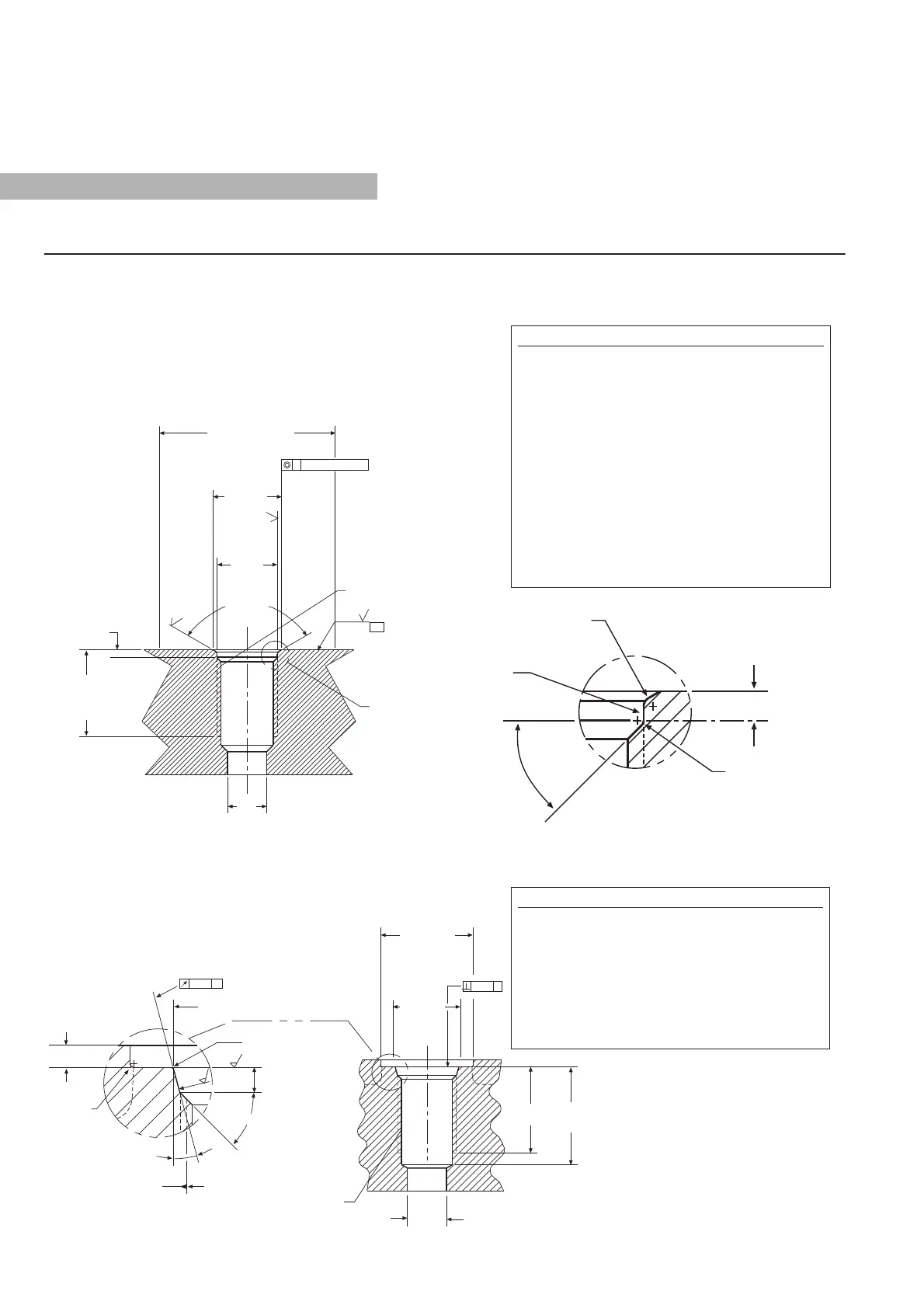
1. Dimensions and tolerances based on ANSI Y14.5-1982.
2. MTS has extracted all pertinent information from
MS33649 to generate this document.
3. PD must be square with surface B within 0.005 FIM
across 2.250 dia minimum.
4. PD must be concentric with 2.250 dia within 0.030 FIM
and with 0.769 dia within 0.005 FIM.
5. Surface texture ANSI B46.1-1978
6. Use O-ring MTS part number 560315 for correct sealing.
7. The thread design shall have VXIğFLHQW threads to meet
strength requirements of material used.
8. Finish counter-bore shall be free from longitudinal and
spiral tool marks. Annular tool marks up to 32
microinches maximum will be permissible.
2.250 in. Minimum dia.
6SHFLğHV6XUIDFH%
120 0 30'
0.094 in.
+ 0.015
- 0.000
See Detail C
81)%7KUHDG
6HH1RWHV$QG
32 in.
32 in.
125 in.
%
1.105 in.
Minimum
)XOO7KUHDG
'HSWK
0.875 in. dia.
+ 0.015
- 0.000
0.769 in. dia.
+ 0.015
- 0.000
0.500 in.
dia.
0.005 in. dia., FIM$
45 5
15 1
0.094 in. max.
0.008 in.
0.004 in.
0.125 in.
0.125 in.
81)%7KUHDG
R
0.813 in. dia.
0.002 in.
0.106 in.
0.008 in.
$
0.008
$
0.004
$
R0.015 in.
max.
3LWFK
dia.
1.180 in.
Recommended
Minimum
6SRWIDFH
'LDPHWHU
See Note 1
0.866 in. dia.
Minimum
See Note 2
1.100 in.
See Note 4
1.250 in.
See Note 3
See Note 4
LQGLD5HI
See Note 4
6$(3RUW6L]H
LQ5HI
See Note 8
0.030 in. 0.010 R
0.020 in. R
Maximum
45 5
E S
E
ES
1. If face of port is on a machined surface, dimensions
1.180 and 0.094 need not apply as long as R0.008/0.004
is maintained to avoid damage to the O-ring during
installation.
2. Measure perpendicularity to A at this diameter.
3. This dimension applies when tap drill cannot pass
through entire boss.
4. This dimension does not conform to SAE J1926/1.
tai
Temposonics
®
R-Series V Profinet RT & IRT
Operation Manual
 Loading...


