Temposonics
®
R-Series V SSI
Operation Manual
I 26 I
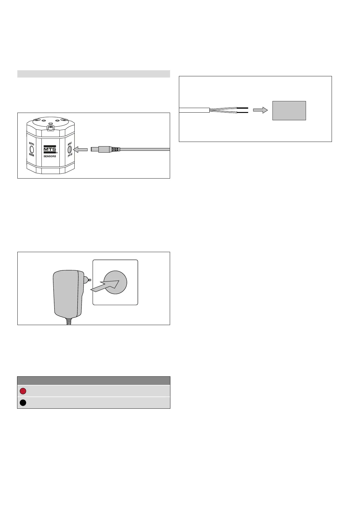
5.3.2 Connection of TempoLink smart assistant to power supply
Connect the barrel connector of the power supply to the connection
point labeled “INPUT 24 VDC” on the TempoLink smart assistant
(Fig. 39).
2. Connection via the cable with barrel connector and pig-tail
Connect the cable to a power supply according to the connector
wiring in Fig. 41 (Fig. 42).
There are two ways to connect the TempoLink smart assistant to a
power supply:
1. Connection via the plug-in power supply with plug adapters
Attach the plug attachment suitable for your country to the plug.
Insert the plug into the outlet (Fig. 40).
Fig. 39: Connection of power supply to the TempoLink smart assistant
Fig. 40: Connection of the plug-in power supply to the outlet
Fig. 41: Connector wiring cable
Fig. 42: Connection of cable with barrel connector and pig-tails
Connection to
power supply
Cable Function
RD
+24 VDC
BK
DC Ground (0 V)

 Loading...