2200LZJE-HO-C6-N_2013.12.
Chapter 5 Maintenance
Compound 2-stage Screw Compressor 2016**C 5.7 Reassembly
5-55
5.7.10 Balance Piston Cover and High-stage Unloader Cylinder
The 2016**C model has the unloader cylinder 【60-2】 also on the high-stage. To facilitate the
assembly work, attach the unloader cylinder 【60-2】 to the balance piston cover 【60-2】 first, and then
attach the united body to the high-stage suction cover 【5-2】.
The balance piston cover and unloader cylinder are often omitted from disassembly unless specifically
needed. Accordingly, steps a) through d) below shall apply when they have been disassembled.
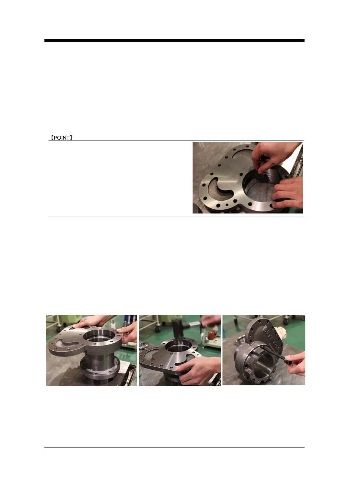
a) Attach the O-ring 【63】 to the O-ring groove provided on the surface of the balance piston cover
where the unloader cylinder is to be attached (Photo 100).
According to the design change on October 1996, the
place O-ring 【63】 is attached has been changed
from the opening with chamfered to the current
position indicated in photo101. At the same time the
same design modification was applied to low-stage
bearing cover. Refer to the next article 5.7.11 in this
chapter.
Photo 100
b) Align the balance piston cover with the unloader cylinder. A gasket cannot be inserted between the
aligning flange surfaces of the balance piston cover and unloader cylinder. So, as shown in Photo
101, thinly and evenly apply special synthetic rubber liquid gasket onto the mating flange surface of
the unloader cylinder at the inner radius from the center positions of the bolt holes.
c) As O-ring is inserted, attach the balance piston cover while tapping its flange surface with a soft
hammer (as shown in Photo 102).
d) When mating the both flange surfaces, also align the bolt holes. Fasten the two hexagon socket
head cap screws 【61】, one at the position shown in Photo 103 and the other at the position spaced
two bolt holes apart from it.
Photo 101 Photo 102 Photo 103
e) Fit the O-ring 【73-2】 in the O-ring groove at the end of the unloader push rod 【67-2】 where the
unloader piston is to be attached.

 Loading...