2200LZJE-HO-C6-N_2013.12.
Chapter 2 Configuration and Specifications of Compressor
Compound 2-stage Screw Compressor 2016**C 2.5 Mechanisms
2-13
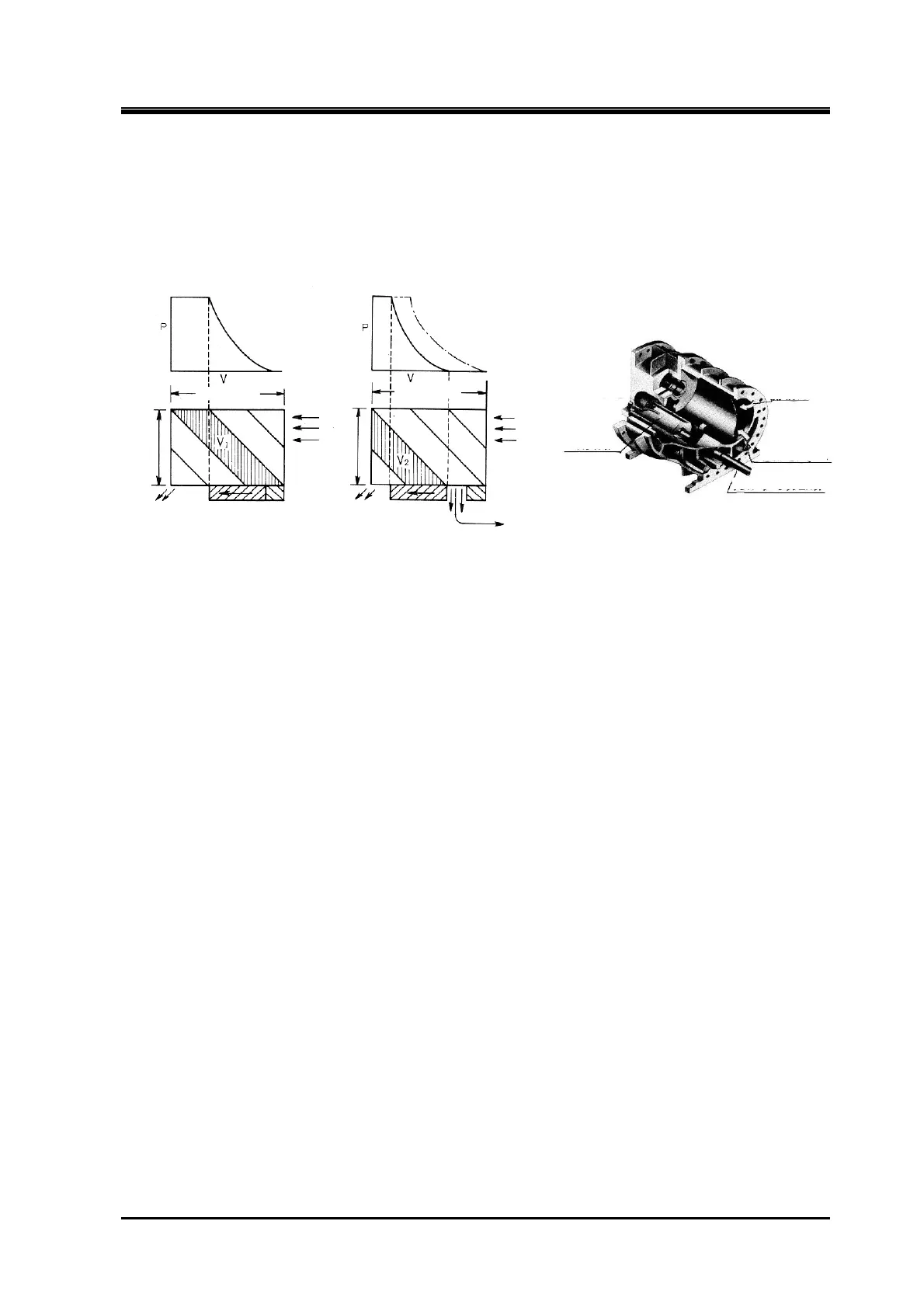
2.5.6 Capacity Control Mechanism
The capacity control mechanism, by moving a slide valve, lets suction gas (immediately before
compressed) bypass and advance to the suction side, to help shorten the rotor portion used for
compression. The slide valve is located at the bottom of the casing in which the rotors mesh together,
and is constructed to move parallel to the rotor shaft. This movement is changed by a cam mechanism
into rotation movement. Its position (namely, capacity control ratio) is indicated externally and, at the
same time, fed back to the automatic control circuit by changing the electric resistance.
Figure 2-13 Capacity Control Mechanism
2.5.7 Bearing
For the load acting on the rotor perpendicular to the shaft, sleeve-type white metal-lined bearings are
used. For the load acting along the shaft direction, face-to-face combination type of angular contact ball
bearings are used.
Special care is taken to cope with the load acting along the shaft direction. Because the M rotor is a
kind of helical gear and also because the thrust force produced by discharge pressure is larger than
that for F rotor, the load applied onto the M rotor is reduced by using not only a thrust bearing but also a
balance piston that applies pressure from the opposing direction.
2.5.8 Seal
A seal which is generally called a mechanical seal is used. The mechanical seal, fully immersed in oil,
rotates and provides complete sealing function and cooling effect.
For example, the BBSE (Balance Bellow Single Seal) which is currently used as standard seal,
employs a stationary ring (mating ring) made of cast metal, a rotating ring made from carbon, and
O-rings for the packing.
Figure 2-14 Slide Valve in the
Rotor Casing
Rotor length Rotor length
Discharge
Discharge
Suction
Suction
Slide valve
Slide valve
Fixed end
Unloader
slide valve
Suction
gas
Re-suctioned gas
Unloader push rod
Volume V
1
at moment when suction-side
port is closed during full load
Volume V
2
at moment when suction-side port for gas
returning to suction-side is closed during partial load

 Loading...