2200LZJE-HO-C6-N_2013.12.
Chapter 5 Maintenance
Compound 2-stage Screw Compressor 2016**C 5.6 Overhaul
5-36
5.6.16 Low-stage Suction Cover and Side Bearings
5.6.16.1 Disassembly
a) While the compressor is being lifted for disassembly, remove 6 to 8 screws 【2-1】 from its bottom.
b) To pull out the oil injection pipe 【85】 that supplies lubricant for injection to the unloader slide valve,
remove the fastening bolts 【166】 of the oil injection pipe retainer 【164】 located at the lower area
of the high-stage.
c) Remove the oil injection pipe retainer.
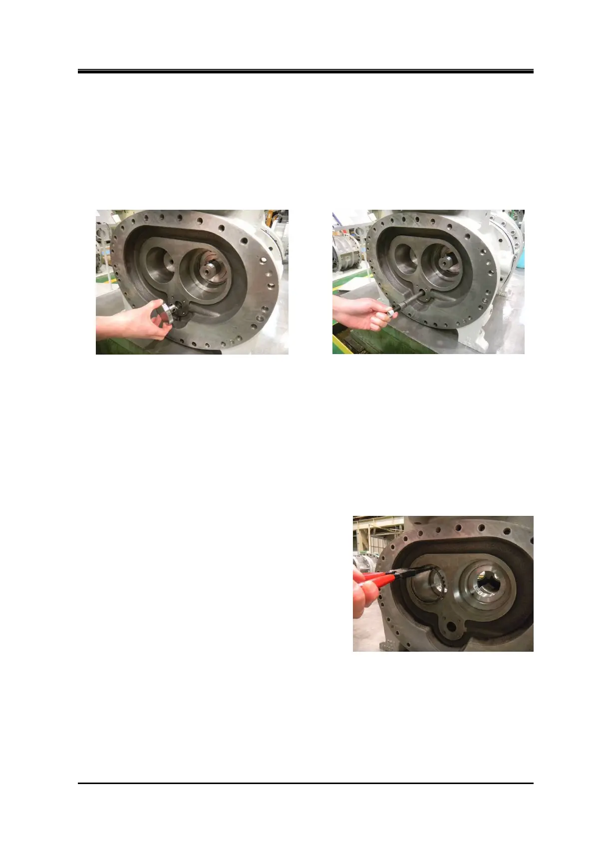
Photo 054 Removal of Oil Injection Pipe Retainer Photo 055 Pulling Out Oil Injection Pipe
d) The oil injection pipe hole is tapped. Insert a screw 【2-1】, and pull out the pipe.
e) Remove all the hexagon socket head cap screws 【2-1】. Then, drive alignment pins 【3-1】 into the
rotor casing 【1-1】.
f) Screw hexagon socket head cap screws 【2-1】 into the two screw holes on the rotor casing flange,
to push the suction cover flange evenly.
g) When a gap is created, peel up the gasket by using a knife or a spatula. Attach it to the suction
cover.
h) When a gap gets spread to a full length of the screws, release the engagement of the rotor shaft
and side bearing by sliding on the surface plate parallel with the axis. The rotor may also be pulled
out simultaneously. Take care.
i) To take out the side bearing 【28-1】, remove the stop
ring 【29-1】 and tap the rotor side.
5.6.16.2 Inspection
Check for wear or embedded foreign matter on the sliding surface inside the side bearing.
If the mating rotor shaft is worn, even when the inner diameter of the side bearing is dimensioned
properly, hard pieces of foreign matter are embedded. Replace the bearing with a new one.
Photo 056 Removing the Stop Ring

 Loading...