2200LZJE-HO-C6-N_2013.12.
Chapter 5 Maintenance
Compound 2-stage Screw Compressor 2016**C 5.7 Reassembly
5-65
b) In a normal state where the capacity control oil pressure pipe is not opened, move the unloader
piston by using a manual capacity control circuit. When the control power is turned on, keep the
indicator cover attached to avoid electrical shock. After the position of the piston is determined, turn
off the control power and conduct lockout/tagout. After that, remove the indicator cover and fix the
indicator needle.
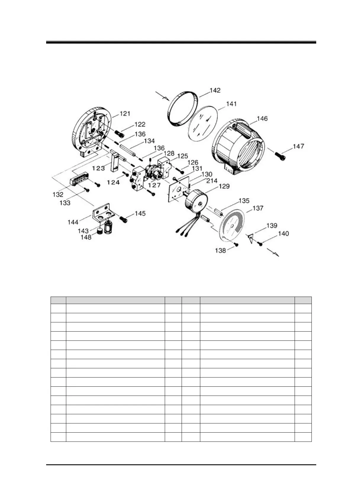
Figure 5-16 Development View of the 2016**C Standard-type High-stage Indicator
Table 5-12 Unloader Indicator Components (Standard type)
No. Part name Qty. No. Part name Qty.
121
Micro-switch base plate 1
136
Potentiometer mounting screw 3
122
Hexagon socket head cap screw 3
137
Indicator dial 1
123
Micro-switch set plate 1
138
Indicator dial screw 2
124
Philips screw 2
139
Indicator needle 1
125
Micro-switch 2
140
Indicator needle screw 1
126
Philips screw 4
141
Indicator glass 1
127
Micro-switch cam 1
142
Indicator glass spacer 1
128
Set screw 1
143
Electric wiring connector 1
129
Potentiometer 1
144
Connector support 1
130
Potentiometer set- plate 1
145
Hexagon socket head cap screw 2
131
Philips screw 3
146
Indicator cover (2) 1
132
Terminal block 1
147
Hexagon socket head cap screw 3
133
Philips screw 2
148
Plug 1
134
Potentiometer support arm [1] 2
214
Spring pin 1
135
Potentiometer support arm [2] 2 265-2 Spring washer 7

 Loading...