StarLink
™
SLE Commercial Series Alarm Communicators -- Installation Instructions 13
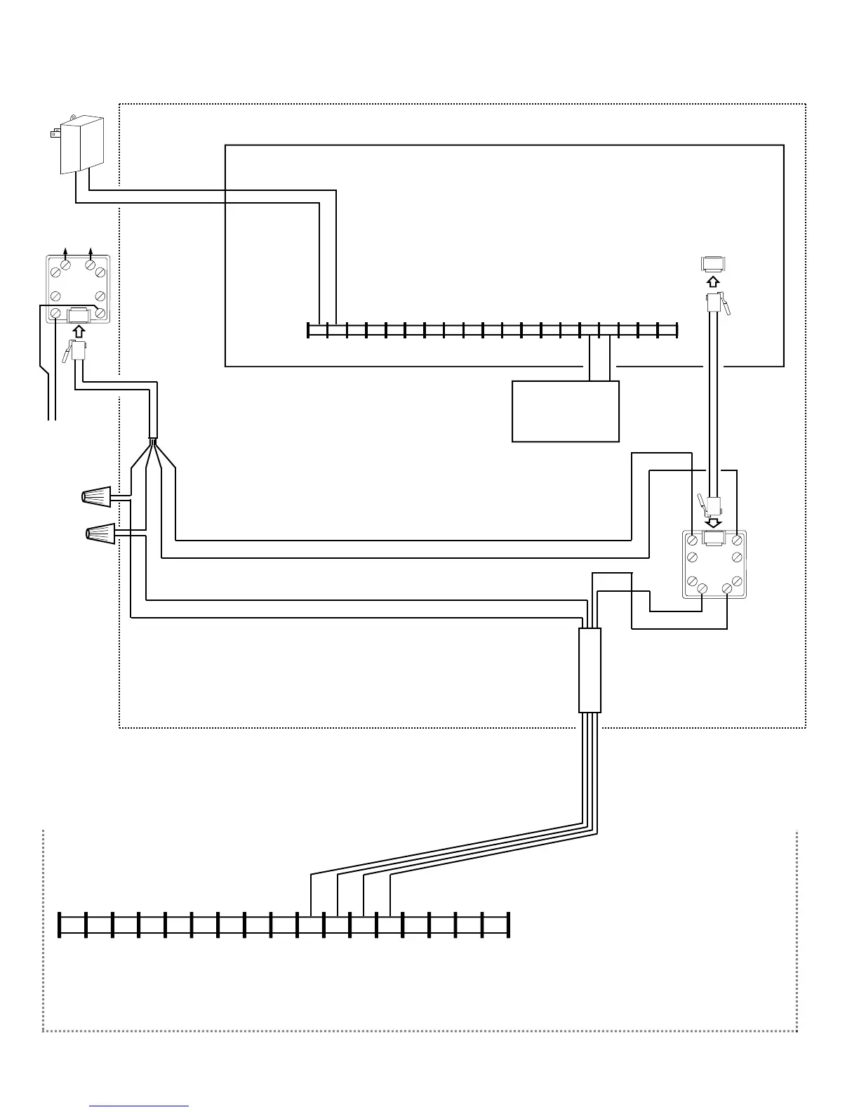
Wiring Diagram for BACKUP Reporting Configuration
GEM-P801 Control Panel
CONTROL PANEL PC BOARD
GRN
RED
BRN
GRAY
(CONTROL PANEL HOUSING)
6 7 8
17 16 15 14 13 12 11
9
10 2
3 4 5
1
19 18
AUX POWER
(–) (+)
16VAC
*For StarLink
module terminals
1 and 2: May be
wired directly to
Aux Power of the
control panel
when 65mA
standby current is
available.
HOME
PHONES
TO TELCO
RJ31X
TELCO
T300
RJ31X
RING TIP
RING TIP
16VAC
Transformer
GRN
RED
YELLOW
BLACK
*Refer to section "SUPPLYING POWER".
6 7 8 15 14 13 12 11 9 10 2* 3 4 5 1*
+12V
(–)
PGM1 PGM2 PGM3 IN1 IN2 GND IN3 RING TIP
17 16
RTS
(R)
PANEL
TX (B)
PANEL
RX (G)
CTS
Y
StarLink Radio Terminals
PANEL
RING (+)
PANEL
TIP (–)
(STARLINK RADIO HOUSING)
(CONTROL PANEL HOUSING)
TELCO QUAD WIRE
Optional: When Power Supply
SLE-ULPS-R is not used,
connect Panel Aux Power to
StarLink terminals 1 and 2
(observing polarity)
All connections are
power limited except
AC Mains, Telco and
battery terminals.
Terminals 14-17: No
connections permitted.

 Loading...


