2 StarLink
™
SLE Commercial Series Alarm Communicators -- Installation Instructions
SPECIFICATIONS
The following specifications apply to all StarLink radio mod-
els unless otherwise stated:
Electrical Ratings for +12V (all models powered by the
control panel)
Input Voltage: 11-15VDC (power-limited output from Listed
control panel)
Input Current: 65mA with peak RF transmission current of
400mA for models SLe-GSM, SLe-GSM-3/4G, SLE-CDMA
and the SLE-CDMA-FIRE; (80mA with peak RF transmis-
sion current of 400mA for models SLe-GSM-8D-3/4G and
the SLE-CDMA-8D)
Electrical Ratings for the IN 1 Burg/Fire Input:
Input Voltage: 9-15VDC
Maximum Input Current: Up to 2mA from FACP NAC circuit
Electrical Ratings for IN 2 and IN 3:
Maximum Loop Voltage: 15VDC
Maximum Loop Current: 1.2mA
End of Line Resistor (EOLR) Value: 10K (2 req'd)
Electrical Ratings for 3 PGM Outputs:
Open Collector Outputs: Maximum Voltage 3V when ac-
tive; 15V maximum when not active
Maximum PGM Sink Current: 50mA
Physical (W x H x D)
Plastic Housing: 8 x 5-
29
/
64
x 1½" (20.3 x 13.9 x 3.8cm)
Mounting: Plastic housing includes three keyhole slots for
triple gang boxes (see scale template on page 19);
Environmental
Operating Temperature: 0°C - 49°C (32°F - 120°F)
Humidity: Maximum 93% Non-Condensing
Indoor use only
TERMINAL DESCRIPTIONS
Configure all inputs and outputs using the Management
Center screen (located at www.napconoc.com). Located at
the bottom of the StarLink radio PC board, the 17 terminals
are described as follows:
TB1: PWR (+12V)
(Refer to section "STEP 4: APPLY POWER")
TB2: PWR GND (–)
(Refer to section "STEP 4: APPLY POWER")
TB3: PGM1 (–): Open collector output. PGM1 is nor-
mally on (active low). When it is triggered (for ex-
ample, a trouble is detected) it becomes open col-
lector/high. To have a zone dedicated to an Star-
Link radio trouble, insert one side of the end of line
resistor into this PGM1 terminal, and wire the other
side of the resistor to the positive terminal of the
zone.
TB4: PGM2 (–): Open collector output. This output is
defaulted as "Fail to Communicate", and is normally
open collector/high. When a report fails to com-
municate anywhere in the communications path, the
output is active low.
TB5: PGM3 (–): Open collector output. This output is
defaulted as "Telephone Line Cut". When the tele-
phone line voltage is correct, the output is open col-
lector/high; when the telephone line voltage is too
low, the output is active low.
TB6: IN 1: Active high input for wiring to the control
panel bell output. When this input detects a pulsing
temporal 3 high, it sends a Fire alarm; a pulsing
temporal 4 (CO Alarm), a CO alarm is sent. When
used, these conductors must be run in conduit (max
20 feet for Commercial Fire, and 3 feet for Residen-
tial Fire). Do not use for Burglary applications. For
this input to report to a central station, the StarLink
radio must be configured with the central station
telephone number and correct reporting formats and
codes.
TB7: IN 2: See TB9, below.
TB8: GND: Common ground terminal.
TB9: IN 3: Both terminals IN 2 and IN 3 by default are
supervised end-of-line resistor inputs that can be
triggered with N/O or N/C relay contacts. Wire the
common ground terminal GND (terminal TB8) to the
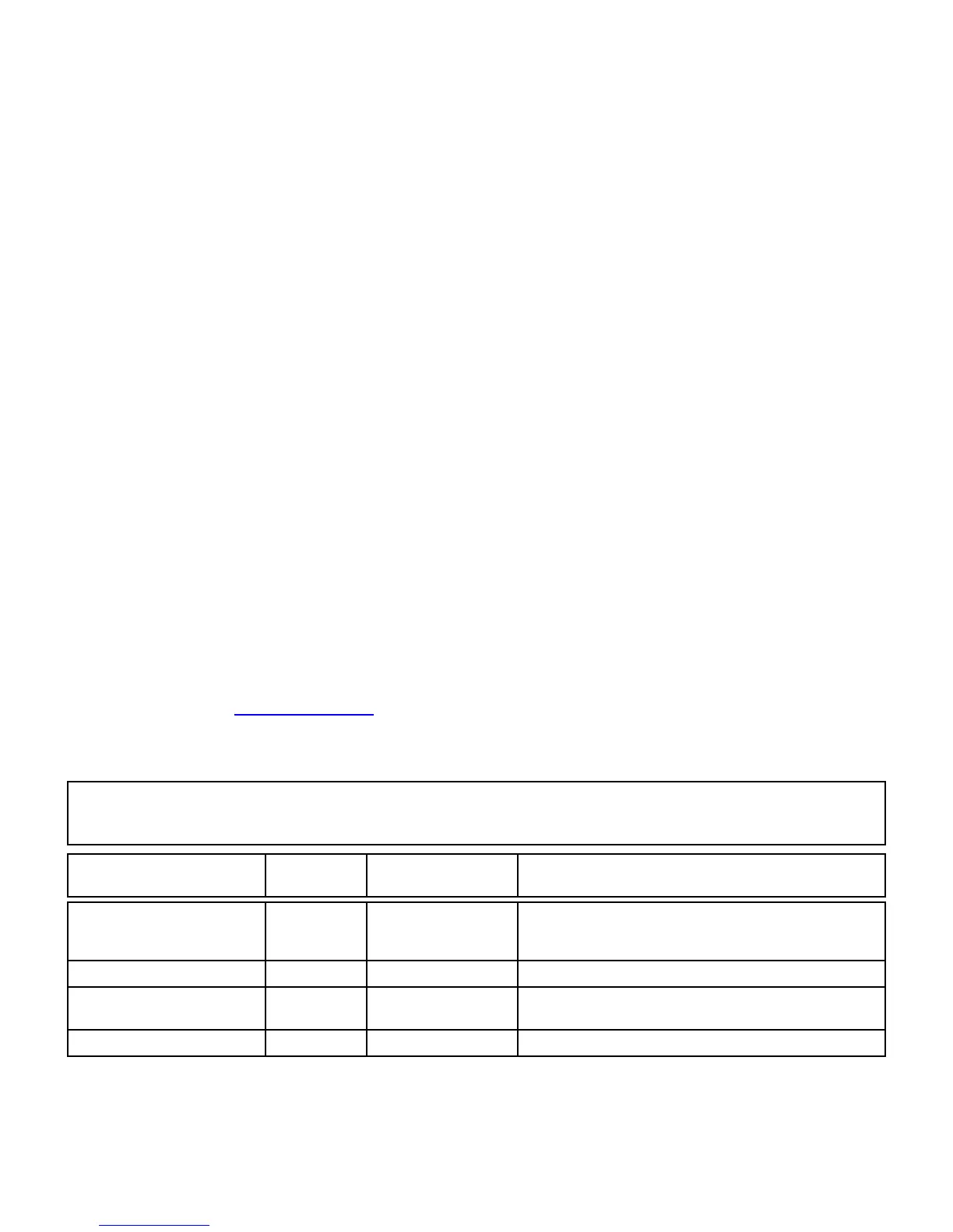
NOTICE TO AUTHORITIES HAVING JURISDICTION, USERS, INSTALLERS,
DEALERS, AND OTHER AFFECTED PARTIES
FIRE PROGRAMMING OPTION
PERMITTED IN
UL864? (Y/N)
AVAILABLE SETTINGS REQUIRED UL 864 SETTINGS
Unattended Remote Downloading No Enable / Disable
Disabled (Jumper 1 installed). Also required for Commercial / Burgla-
ry installations. Note: See page 7 "Configuration Download / Firm-
ware Updates" for jumper instructions.
IN2 and IN3 Unsupervised No Supervised / Unsupervised Supervised (Jumpers 4 and 5 installed)
7 Day Supervision, Radio to NOC No
200 seconds, 5 minutes,
60 minutes, 7 days
200 seconds, 5 minutes
4/2 Reporting No 4/2 or Contact ID Contact ID

 Loading...


