StarLink
™
SLE Commercial Series Alarm Communicators -- Installation Instructions 3
relay common. When used as arm/disarm status
input, a low indicates "armed" and a high indicates
"disarmed". For these inputs to report to a central
station, the radio must be configured with the cen-
tral station telephone number and correct reporting
formats and codes. See table on page 20 for more
information.
TB10: TIP: See TB11, below.
TB11: RING: Terminals TIP and RING: When used for
backup reporting, the house tip and ring telephone
wires must be routed from the outside to these ter-
minals. Under normal back up conditions, these
terminals are internally wired to the PANEL TIP and
PANEL RING terminals, allowing all transmissions
to the central station to be monitored. These wires
are monitored for voltage such that if voltage falls
below 1.5V, a Telco Line Fault trouble is detected,
and the StarLink radio applies telephone line volt-
age to the control panel Tip and Ring allowing it to
receive and transmit any alarms sent by the control
panel.
TB12: PANEL RING: See wiring diagrams.
TB13: PANEL TIP: See wiring diagrams.
Note: TB14-TB17 no connections permitted by UL.
TB14: RTS (R): See TB17 below.
TB15: PANEL TX (B): See TB17 below.
TB16: PANEL RX (G): See TB17 below.
TB17: CTS (Y): No connections permitted.
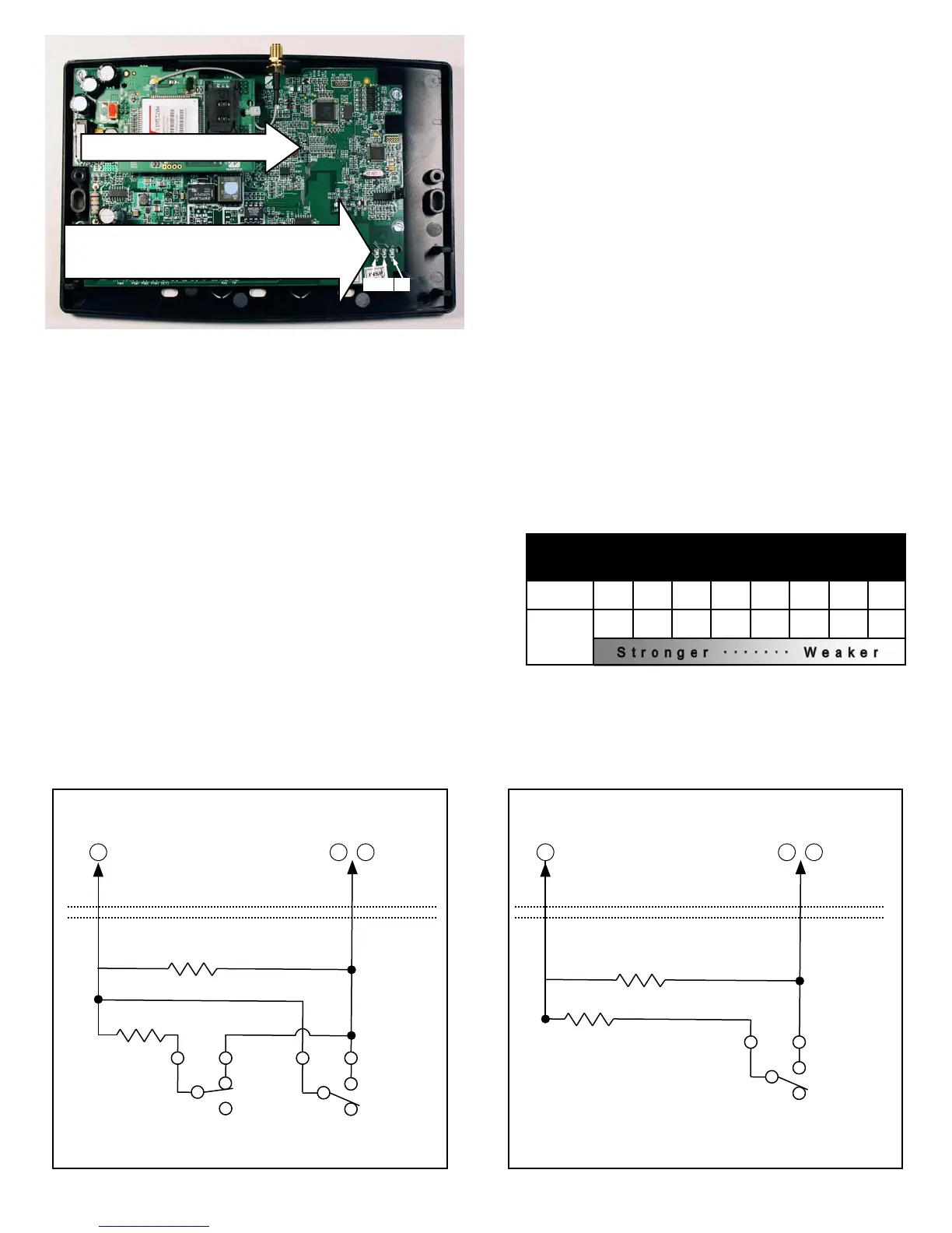
LED DESCRIPTIONS
The PC board contains several LED's, as follows:
GREEN RF SIGNAL STRENGTH LED
Labeled "D3", this LED is located at the lower right cor-
ner of the PC board.
Every 30 seconds, the StarLink radio receiver section
turns on and listens to the cell tower. Depending on the
signal strength detected, it will blink the Signal Strength
LED from 1 to 8 times, providing a signal strength indica-
tor that is updated constantly and is always displayed.
Refer to Coverage Table below.
Green LED Operation
Signal strength (as received by the radio) is displayed by
this LED blinking 1 to 8 times at a constant rate (with a
short delay between blink cycles). Acceptable power
level is greater than or equal to -91dBm (minimum 4
blinks at the mounting location).
YELLOW OPERATIONAL STATUS LED
Labeled "D4", this LED is located at the bottom right of
the PC board. Operation is as follows:
GREEN RF SIGNAL STRENGTH LED
RADIO RECEIVER COVERAGE TABLE
LED Blinks 8 7 6 5 4 3 2 1
-55 -65 -75 -85 -91 -95 -99 -105
Power
(dBm)
LED LOCATIONS
D4
D3 D5
RED DIAGNOSTIC LED (Labeled "D7")
YELLOW OPERATIONAL STATUS LED (Labeled "D4")
GREEN RF SIGNAL STRENGTH LED (Labeled "D3")
RED TROUBLE LED (Labeled "D5")
Supervised Fire / Burg Input
10K
10K
C C N/C
Alarm
N/C
TBL
To StarLink
Terminals
IN2 (TB7)
-or-
IN3 (TB9)
Radio GND
(TB8)
The EOLR must be installed and located within the control panel housing.
(Radio)
(Alarm Panel)
8 7 9
-or-
Supervised Arm / Disarm Input
10K
10K
C
Open = Disarmed
Closed = Armed
The EOLR must be installed and located within the control panel housing.
Radio GND
(TB8)
(Radio)
(Alarm Panel)
8 7 9
-or-
To StarLink
Terminals
IN2 (TB7)
-or-
IN3 (TB9)

 Loading...


