StarLink
™
SLE Commercial Series Alarm Communicators -- Installation Instructions 5
locations have been shown to have a detrimental effect
on signal strength.
A fair amount of care may be required to mount the ra-
dio so as to achieve an optimal RF path. The installer
should spend as much time as needed to obtain the
highest signal level possible.
For Commercial Burglary installations, install in accord-
ance with UL 681, Standard for Installation and Classifi-
cation of Burglary and Holdup Alarm Systems. Installa-
tion shall also be in accordance with UL 827, Standard
for Central-Station Alarm Services, and UL 1641, Stand-
ard for Installation and Classification of Residential Bur-
glar Alarm Systems.
a. Before applying power, be sure to connect the
antenna. Temporarily connect power to the radio
from a fully charged 12V (4AH minimum) battery.
DO NOT mount the StarLink radio at this time.
b. Position the unit in the desired mounting location,
with antenna oriented vertically. The signal strength
is displayed by the Green "Signal Strength LED" la-
beled "D3" (located at the lower right corner of the
PC board). The GSM radio tower signal strength
may fluctuate from day to day, therefore it is best to
try to find a mounting location where the LED pro-
vides a minimum of 4 blinks.
c. Once a location has been selected based on signal
coverage, permanently secure the unit using #8
screws (not supplied) in the two mounting holes.
WARNING: To ensure user safety and to satisfy FCC
RF exposure requirements, this unit must be installed so
that a minimum separation distance of 60cm (24") is al-
ways maintained between the antenna of the transmitting
device and nearby persons. Use ONLY the existing an-
tenna supplied by radio to comply with this warning
(Exception: The SLE-ANTEXT extended antenna with
15 feet of cable).
STEP 3: WIRING (PRIMARY AND BACKUP MODES)
22-gauge wire may be used if mounted up to 50 feet from
the control panel, and 18-gauge wire should be used for up
to 100 feet. Reference the wiring diagrams further in this
manual. See the section CONTROL PANEL PROGRAM-
MING further in this manual.
NOC Originated
Alarms
Contact ID
Event Data
Sent
Pulse Format
Event Code
Sent
Initiated By Comments
Supervisory Fail
E356 A00 Zn000 99
Automatically by NOC if fail to receive
any signal from StarLink radio within
Supervisory Timeout duration.
For Auto Enroll, uses captured telephone
number, Sub ID and format. For Dealer
Programmed, uses entered telephone
number, Sub ID and format.
Press to Send
Test Signal
E601 A00 Zn000 98
Manually by dealer from the Manage-
ment Center Signal Log screen
(located at www.napconoc.com).
Sends test into CS receiver.
Same comment as above.
Press to Send
Radio Test
Not Applicable
Nothing sent to
CS receiver
Not Applicable
Manually by dealer from the Manage-
ment Center Checkins screen (located
at www.napconoc.com). Sends a com-
mand to the StarLink radio to force a
check-in to the NOC.
----
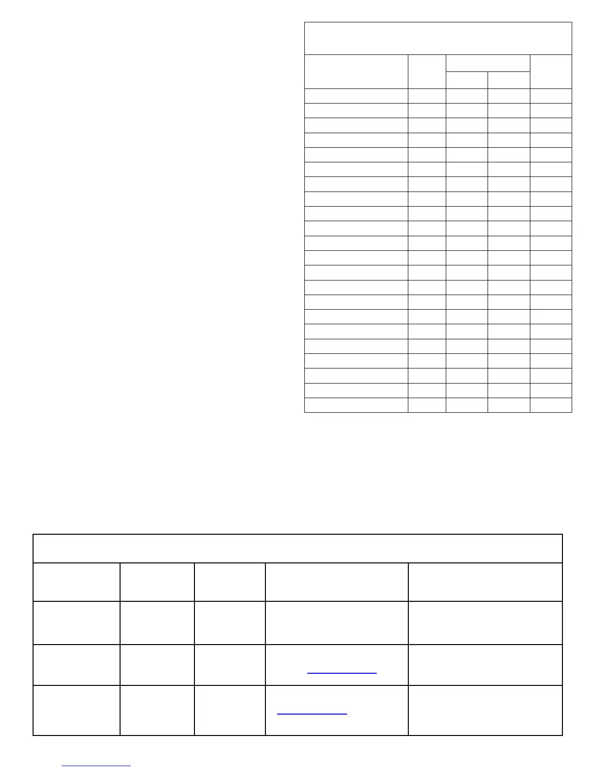
SIGNALS ORIGINATED AT THE NOC
STARLINK RADIO RELATED EVENT
REPORT CODES (Contact ID by default)
EVENT AREA
CONTACT ID
CODE ZONE #
IN 1 Fire
0 E110 990 1A
IN 2 Panic
0 E120 992 22
IN 3 Trouble
0 E300 993 F3
Low Battery/Voltage
0 E302 994 F4
Tamper Trouble
0 E341 995 F5
Line Cut
0 E352 996 F6
Reboot
0 E625 997 F7
IN 1 CO (Carbon Monoxide)
0 E162 998 18
Panic Alarm*
E123
Holdup Alarm*
E122
Medical Alarm*
E100
24 hour Aux. Alarm*
E150
24 hour Aux. Restore*
R150
Burg Perimeter Alarm*
E131
Burg Interior Alarm*
E132
Keypad Holdup Alarm (ambush)*
E121
Keypad Panic Alarm*
E123
Keypad Emergency Alarm*
E140
Opening*
E401
Closing*
R401
A.C. Trouble*
E301
Tel 1 Fail*
E351
*Not generated by the StarLink radio.
**See table "NOTICE TO AUTHORITIES HAVING JURISDICTION..." on page 2.
PULSE
4/2**
Cover Tamper
The SLE series radios in the plastic housings are provided
with a front tamper switch. Note: The tamper switch on
the radio PC board is always functional and requires no
programming.

 Loading...


