Chapter 9 Digital Routing and Clock Generation
M Series User Manual 9-8 ni.com
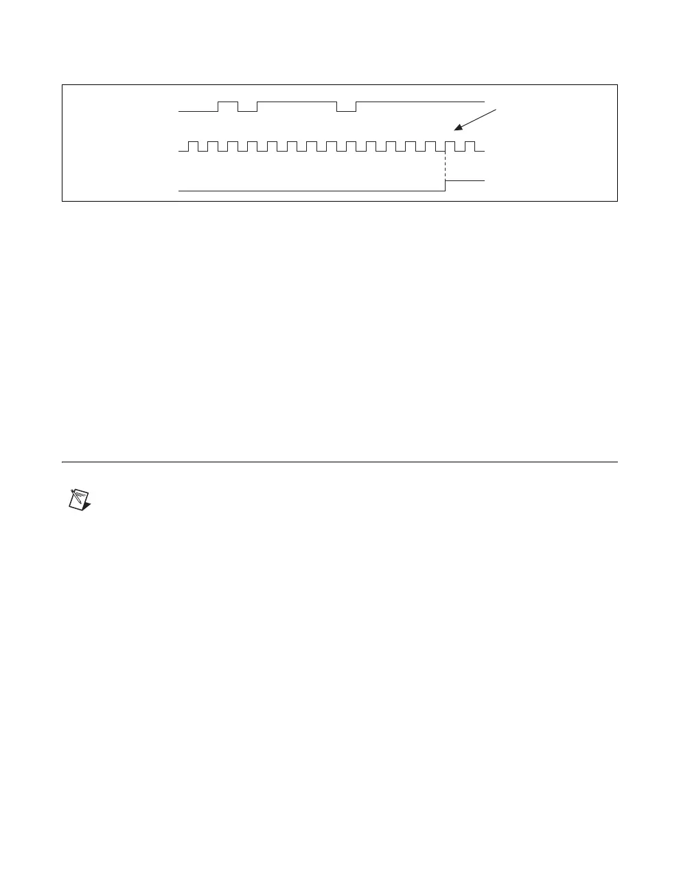
Figure 9-3. Filter Example
Enabling filters introduces jitter on the input signal. For the 125 ns and
6.425 µs filter settings, the jitter is up to 25 ns. On the 2.56 ms setting,
the jitter is up to 10.025 µs.
When a PFI input is routed directly to RTSI, or a RTSI input is routed
directly to PFI, the M Series device does not use the filtered version of
the input signal.
Refer to the KnowledgeBase document, Digital Filtering with M Series,
for more information about digital filters and counters. To access this
KnowledgeBase, go to
ni.com/info and enter the info code rddfms.
PXI Clock and Trigger Signals
Note PXI clock and trigger signals are only available on PXI/PXI Express devices.
PXI_CLK10
PXI_CLK10 is a common low-skew 10 MHz reference clock for
synchronization of multiple modules in a PXI measurement or control
system. The PXI backplane is responsible for generating PXI_CLK10
independently to each peripheral slot in a PXI chassis.
PXI Triggers
A PXI chassis provides eight bused trigger lines to each module in a
system. Triggers may be passed from one module to another, allowing
precisely timed responses to asynchronous external events that are being
monitored or controlled. Triggers can be used to synchronize the operation
of several different PXI peripheral modules.
On M Series devices, the eight PXI trigger signals are synonymous with
RTSI <0..7>.
1 2 3 1 4 1 2 3 4 5
RTSI, PFI, or
PXI_STAR Terminal
Filter Clock
(40 MHz)
Filtered Input
Filtered input goes
high when terminal
is sampled high on
five consecutive filter
clocks.

 Loading...