Chapter 6 Digital I/O
M Series User Manual 6-2 ni.com
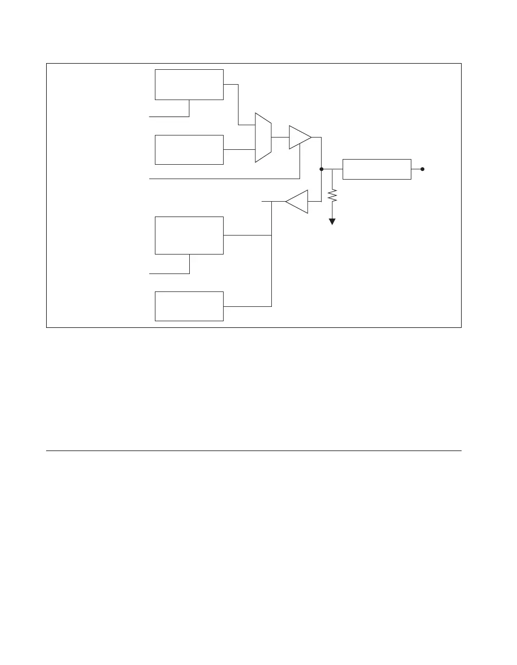
Figure 6-1. M Series Digital I/O Circuitry
The DIO terminals are named P0.<0..31> on the M Series device I/O
connector.
The voltage input and output levels and the current drive levels of the DIO
lines are listed in the specifications of your device.
Static DIO
Each of the M Series DIO lines can be used as a static DI or DO line. You
can use static DIO lines to monitor or control digital signals. Each DIO can
be individually configured as a digital input (DI) or digital output (DO).
All samples of static DI lines and updates of DO lines are software-timed.
P0.6 and P0.7 on 68-pin M Series devices also can control the up/down
input of general-purpose counters 0 and 1, respectively. However, it is
recommended that you use PFI signals to control the up/down input of the
counters. The up/down control signals, Counter 0 Up_Down and Counter 1
Up_Down, are input-only and do not affect the operation of the DIO lines.
DO Sample Clock
DO Waveform
Generation FIFO
DO.
x
Direction Control
Static DI
DI Sample Clock
DI Change
Detection
I/O Protection
Weak Pull-Down
P0.
Static DO
Buffer
DI Waveform
Measurement
FIFO

 Loading...