© National Instruments | 5-33
NI cDAQ-9181/9184/9188/9191 User Manual
• Counter n HW Arm Signal
• Counter n Sample Clock Signal
• Counter n Internal Output Signal
• Counter n TC Signal
• Frequency Output Signal
In this section, n refers to the cDAQ chassis Counter 0, 1, 2, or 3. For example, Counter n Source
refers to four signals—Counter 0 Source (the source input to Counter 0), Counter 1 Source (the
source input to Counter 1), Counter 2 Source (the source input to Counter 2), or Counter 3
Source (the source input to Counter 3).
Note All counter timing signals can be filtered. Refer to the PFI Filters section of
Chapter 4, Digital Input/Output and PFI, for more information.
Counter n Source Signal
The selected edge of the Counter n Source signal increments and decrements the counter value
depending on the application the counter is performing. Table 5-8 lists how this terminal is used
in various applications.
Routing a Signal to Counter n Source
Each counter has independent input selectors for the Counter n Source signal. Any of the
following signals can be routed to the Counter n Source input:
•80MHz Timebase
•20MHz Timebase
• 100 kHz Timebase
• Any PFI terminal
• Analog Comparison Event
• Change Detection Event
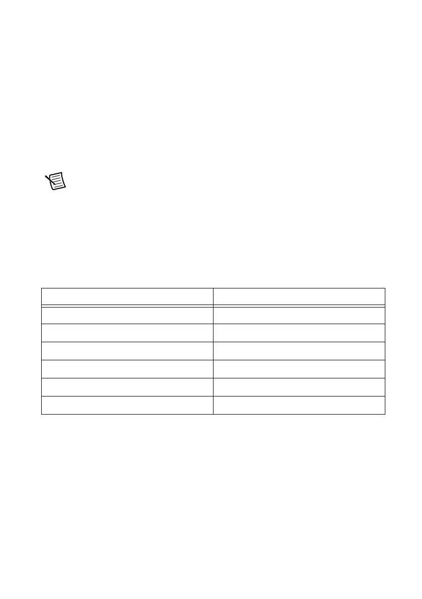
Table 5-8. Counter Applications and Counter n Source
Application Purpose of Source Terminal
Pulse Generation Counter Timebase
One Counter Time Measurements Counter Timebase
Two Counter Time Measurements Input Terminal
Non-Buffered Edge Counting Input Terminal
Buffered Edge Counting Input Terminal
Two-Edge Separation Counter Timebase
 Loading...