PXI Express Onboard LEDs
The PXIe-8394, PXIe-8398, and PXIe-8399 have additional LEDs that provide information
about the status of several PCI Express links.
Each LED is an indicator for four PCI Express lanes. Blink patterns are encoded into each
LED to indicate the number of lanes linked and the link speed. The blink pattern repeats every
two seconds. In general, if the LED is on, it means all four lanes are linked, and the number of
blinks indicates the speed. If the LED is off but blinking on, it means fewer than four lanes are
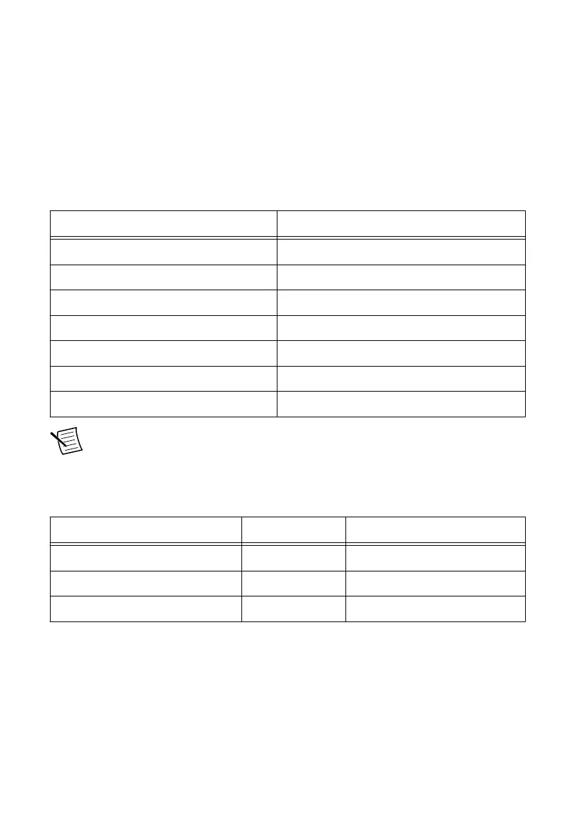
linked, and the number of blinks indicates the speed. The following table lists the patterns.
LED Blink Pattern (Two-Second Period) Meaning
Off No link
On All four lanes linked at PCI Express Gen 3
Primarily on, blinks off twice All four lanes linked at PCI Express Gen 2
Primarily on, blinks off once All four lanes linked at PCI Express Gen 1
Primarily off, blinks on three times One or two lanes linked at PCI Express Gen 3
Primarily off, blinks on twice One or two lanes linked at PCI Express Gen 2
Primarily off, blinks on once One or two lanes linked at PCI Express Gen 1
Note The following table lists the maximum theoretical throughput of PCI Express
lanes. Raw Bitrate is the speed of bits on the wire. Bitrate After Encoding is the
speed of bits after subtracting symbol encoding overhead, and is the max theoretical
throughput. You'll typically get 70% to 80% of the after-encoding rate after protocol
overhead and other detractors.
PCI Express Generation Raw Bitrate Bitrate After Encoding
PCI Express Gen 3 8 Gb/s/lane 7.88 Gb/s/lane
PCI Express Gen 2 5 Gb/s/lane 4 Gb/s/lane
PCI Express Gen 1 2.5 Gb/s/lane 2 Gb/s/lane
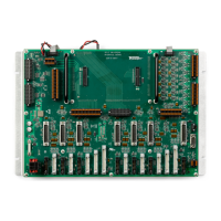
LEDs for Ports 1-4
Onboard link indicators for front panel cable links 1-4 are directly behind the connectors on
the back side of the board, as shown in the following figure. The LEDs represent the lanes of
the port they're adjacent to.
MXI-Express Gen-3 x16 User Manual | © National Instruments | 19
 Loading...